Do you have a question about the Avid Technology SMARTCAL and is the answer not in the manual?
Details product certifications including ATEX, IECEx, and FM standards.
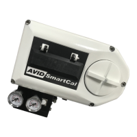
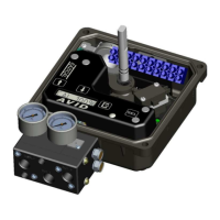
Overview of the electro-pneumatic servo system, its versions (HART/non-HART), and key features.
Explains the non-contact position sensing and microprocessor-based intelligence of the positioner.
Highlights key capabilities such as non-contact feedback, remote control, and local LCD display.
Provides a product decoding matrix to select the correct SmartCal positioner model.
Instructions for direct mounting of the positioner onto a rotary actuator using a modmount bracket.
Steps for mounting a remote positioner and visual indicator on a rotary actuator.
Procedure for mounting the positioner onto a linear actuator, including magnet assembly placement.
Details on connecting pneumatic lines for single and double acting actuators, including port functions.
Guidelines for making electrical connections, including loop signal, analog output, and switch connections.
How to access the calibration menu (ACAL, MCAL, Cofg, Stro) using the CAL button.
Procedure for performing self-adjustments, zero/span calibration, and PID tuning.
Steps to adjust parameters like Flow, Type, FLOP, OPSP, EDb, and LCD settings.
Essential checks covering voltage, electrical, pneumatic, and magnetic feedback before operation.
Answers to common issues like blank LCD, incorrect position display, and oscillation.
List of error codes compatible with previous versions, including Err 3, Err 5, Err 6, and ALR.
Table of LCD messages, their meanings, and corresponding troubleshooting steps.
| Input Signal | 4-20 mA |
|---|---|
| Supply Pressure | 1.4-7 bar (20-100 psi) |
| Ambient Temperature Range | -40 to 85°C (-40 to 185°F) |
| Enclosure Rating | IP66/NEMA 4X |
| Communication | HART |