CRANECO.
280N.MIDLANDAVE.,STE258,SADDLEBROOK,NJ07663WWW.AVIDCONTROLS.COM
12/17/12 TECH-440/D.W.O. 23135 Page 14 of 55
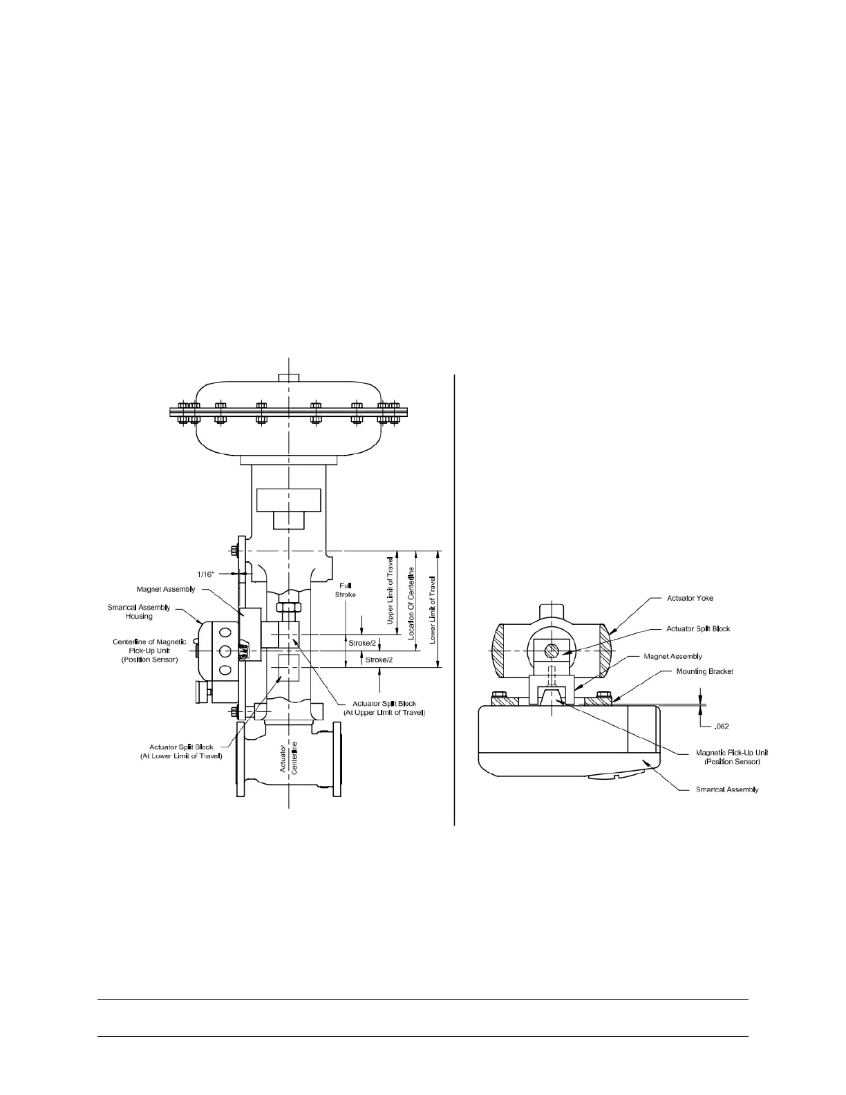
3.3 Mounting Positioner on a Linear Actuator
Step 1. Mount the magnet assembly to the stem of the actuator. A coupler block normally
is needed to extend the magnet assembly outside the yoke area and into the sensing
range of the magnetic pick-up unit.
Step 2. Fasten the mounting bracket to the actuator.
Step 3. Mount the positioner to the mounting bracket. The positioner should be mounted
so the magnetic pick-up unit of the positioner is centered between the limits of the
magnetic assembly’s stroke. After mounting the positioner, the magnet assembly should
be within 1/8” [3.2 mm] from the back of the positioner (1/16” [1.6 mm] is ideal), (See
Figure 3-5)
Figure 3-5
Note: For Fisher actuators model 657 & 667 sizes 34 thru 70, a slotted mounting kit
design can be supplied. This will allow the user to easily center the positioner sensor
between the limits of the magnet assembly’s stroke. Other mounting kits are available
upon request.