CRANECO.
280N.MIDLANDAVE.,STE258,SADDLEBROOK,NJ07663WWW.AVIDCONTROLS.COM
12/17/12 TECH-440/D.W.O. 23135 Page 30 of 55
5 Trouble Shooting
5.1 Preliminary Checks
Before operating the positioner check the
following:
5.1.1. Voltage
The positioner requires a 4-20 mA current source,
with a minimum voltage of 9VDC at its terminals,
over-current protected up to 35VDC.
Current range: 3.2mA to 22mA, accordingly to the following table
(NAMUR NE43):
Loop Current
[mA] Electronics
Spool
valve
HART
comm
0.0 ≤ I < 3.2 OFF OFF OFF
3.2 ≤ I < 3.5 ON OFF OFF
3.5 ≤ I < 3.8 ON OFF ON
3.8 ≤ I ≤ 20.5 ON ON ON
I > 20.5 ON ON ON
5.1.2. Electrical Connection
Check the polarity of the 4-20 mA loop
current loop. The SmartCal terminal strip
visually designates the positive and
negative terminal points for connection
with a “+” and “-”, respectively.
5.1.3. Pneumatic Connection
Single Acting: Output port 1 should be
piped to drive the actuator away from the
valves fail position. Output port 2 should be
plugged. (See Section 3.3)
Double Acting: Output port 1 should be
piped to drive the actuator away from the
valves fail position. Output port 2 should be
piped to drive the actuator towards the
valves fail position. (See Section 3.3)
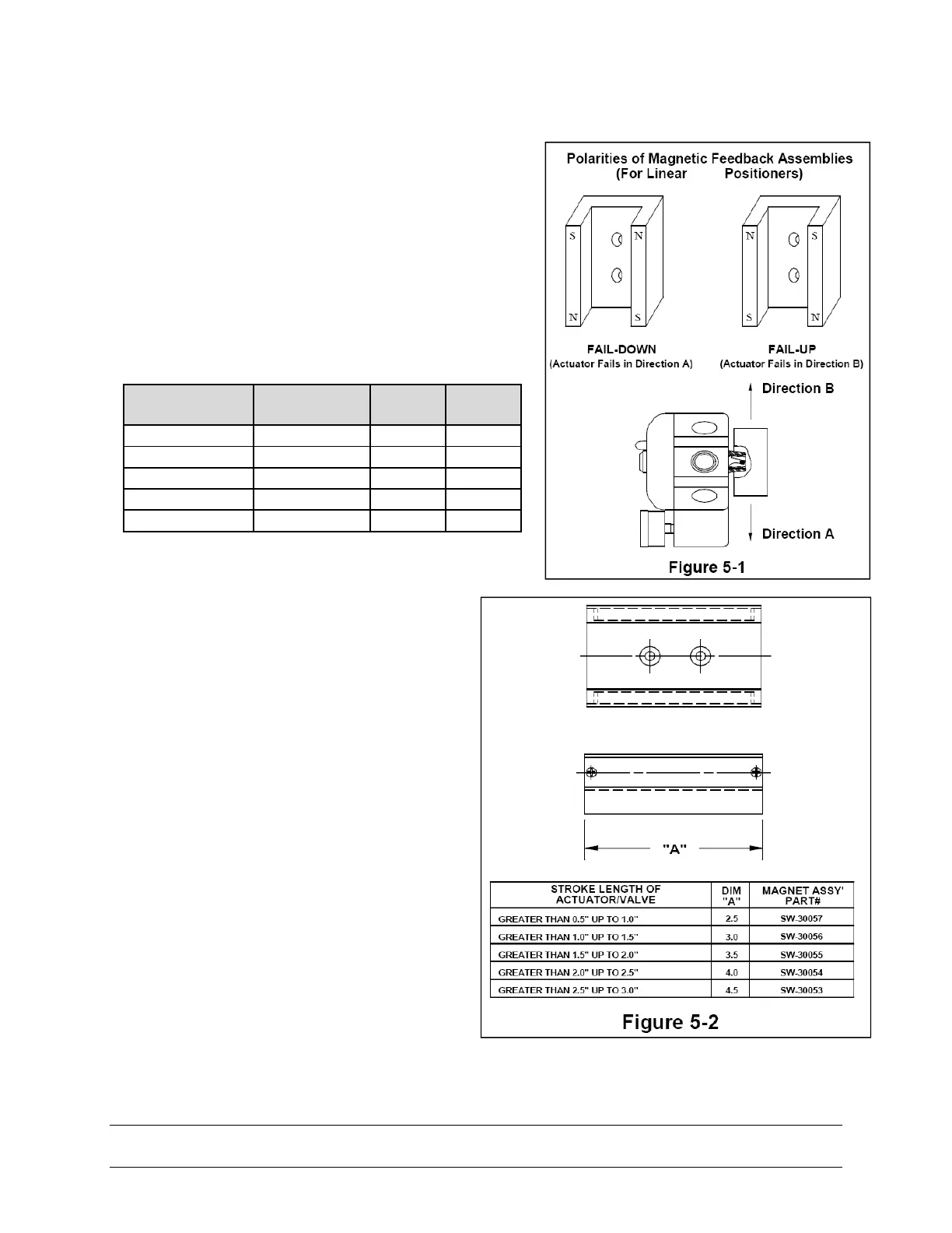
5.1.4. Magnetic Position Feedback
Rotary Positioner: The magnetic beacon
should be set in the proper orientation,
based on the direction of failure. (See
Section 3.1)