6
Connecting Cables
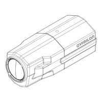
Refer to the camera diagrams in the Overview section for the location of the different
connectors.
To connect the cables required for proper camera operation, complete the following:
1. If there are external input or output devices that need to be connected to the
camera (for example: door contacts, relays, etc), connect the devices to the
camera I/O Terminals.
For more information, see Connecting to Input/Output Devices in the Cable
Connections section.
2. If an external microphone or external video monitor needs to be connected
to the camera, connect the devices to the camera Audio/Video Connector.
For more information, see Connecting to Microphones and Video Monitors
in the Cable Connections section.
3. Connect the Ethernet Port (RJ45 connector) to a network using an Ethernet
network cable. The Link LED will turn on once the camera establishes a link
to the network.
4. Connect power using one of the following methods:
• Power over Ethernet (PoE) Class 3 — If PoE is available, the camera
will automatically be detected when the network cable is connected.
• External Power — Connect an external 12 VDC or 24 VAC power
source to the power connector block.
For more information, see Connecting Power in the Cable
Connections section.
5. Check that the Connection Status LED indicates the correct camera state.
For more information, see the LED Indicators section.
Assigning an IP Address
The camera automatically obtains an IP address by default. Once connected to a
network, the camera attempts to locate and obtain an IP address from a DHCP server. If
this fails, the camera uses Zero Configuration Networking (Zeroconf) to choose an IP
address. When the camera's IP address is set using Zeroconf, its IP address is in the
169.254.0.0/16 subnet.
The camera's IP address settings can be changed using one of the following methods:
 Loading...