WARNING — This product is intended to be powered by a UL Listed Power Unit marked “Class 2”
or “LPS” or “Limited Power Source” with output rated 24VAC±10%, 75 VA min.; 24VDC±10%, 51 W
min. or a 60W Power over Ethernet (PoE++) mid-span injector.
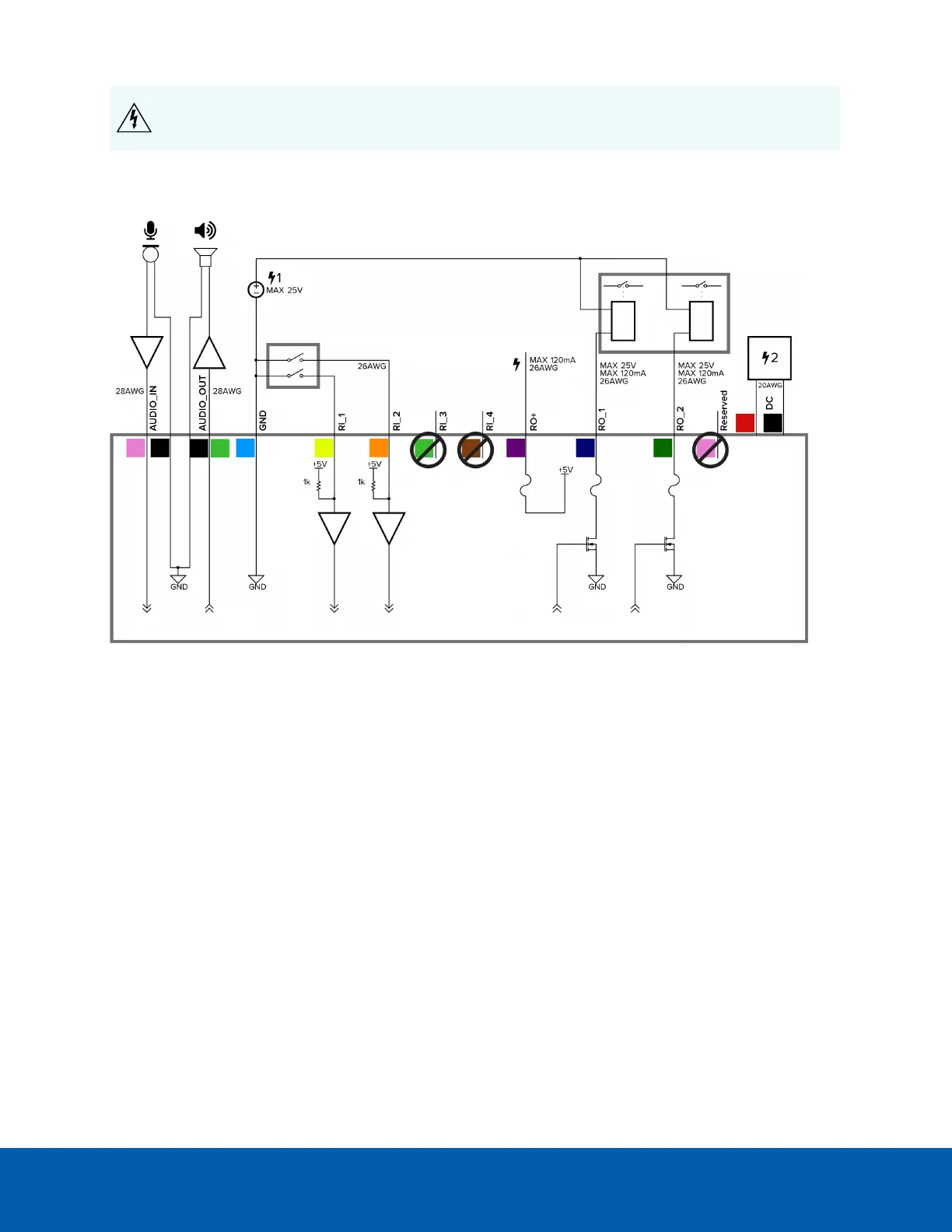
Power supplies and external devices are connected to the camera through the power and I/O wires. The
pinout for the I/O and power wires is shown in the following diagram:
Figure 7: Example application.
l Pink (AUDIO_IN) — Audio Input (line level)
An external power amplifier should be used when connecting speakers and microphones, as shown
in the diagram.
l Black — Audio Ground
l Light Green (AUDIO_OUT) — Audio Output (line level)
l Black — Audio Ground
l Light Blue (GND) — Ground for digital inputs and outputs.
l Yellow (RI_1) — Digital Input, Relay 1. The input voltage must be below 0.7V to register as a low input.
The input voltage should not exceed 5V when high.
l Orange (RI_2) — Digital Input, Relay 2
l Light Green (RI_3) — Unused Wire, do not connect.
l Brown (RI_4) — Unused Wire, do not connect.
l Purple (RO+) — +5V power output from camera.
l Blue (RO_1) — Digital Output
l Green (RO_2) — Digital Output
Connecting to Power and External Devices 28
 Loading...