3-Feb-2015
Table 14 – PicoZed 7010/7020 JTAG Connections
2.10 Power Supplies
2.10.1 Voltage Rails and Sources
PicoZed 7010/7020 is powered through the Micro Header connection between itself and the
carrier card.
There are five regulators that reside on the PicoZed 7010/7020 that provide 1.0V, 1.35V, 1.8V,
3.3V and 0.675V power rails. These voltages are used to power the peripheral devices on the
PicoZed System-On-Module. These regulators are powered from the end user carrier card via the
VIN pins on the Micro Headers and are expected to carry 5V or 12V to the PicoZed System-On-
Module for the input to the regulators.
There are also three bank voltages that are supplied from the end user carrier card to the
PicoZed System-On-Module. Bank 34 (VCCO_34), Bank 35 (VCCO_35) and Bank 13
(VCCO_13) are generated on the end user carrier card and connected to the PicoZed 7010/7020
System-On-Module via the Micro Headers. The voltage at which these banks operate is up to the
carrier card design as all I/O that connect to these banks is exclusive to the Micro Headers (no
on-board device is connected to these banks).
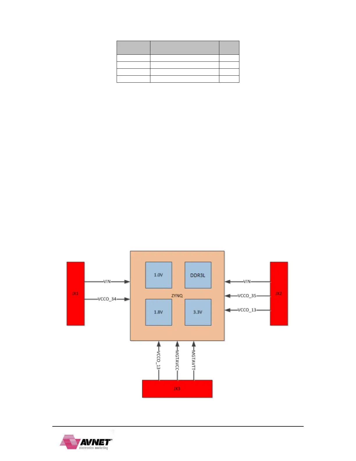
The diagram below shows a high level depiction of the power scheme for PicoZed 7010/7020
System-On-Module.
Figure 5: PicoZed 7010/7020 Power Scheme