3-Feb-2015
2.5 User I/O
2.5.1 Available PS MIO User Pins
PicoZed 7010/7020 provides 8 user PS MIO pins from bank 500 and 12 user PS MIO pins from
bank 501 of the Zynq-7000 AP SoC. The 20 PS MIO pins connect to the Zynq Processor Sub-
System for the implementation of peripheral such as USB, SPI, SDIO, CAN, UART, and I2C.
These I/O pins can also be used as general purpose IO to connect push buttons, LEDs and/or
switches to the Zynq from the carrier card.
Note: The bank 500 PS MIO are shared with the eMMC interface and proper operation of these 8
user PS MIO pins depends on the multiplexer implemented to support the shared interface.
Please review section 2.2.3 eMMC (Multi-Media Controller) for details on the multiplexer
interface.
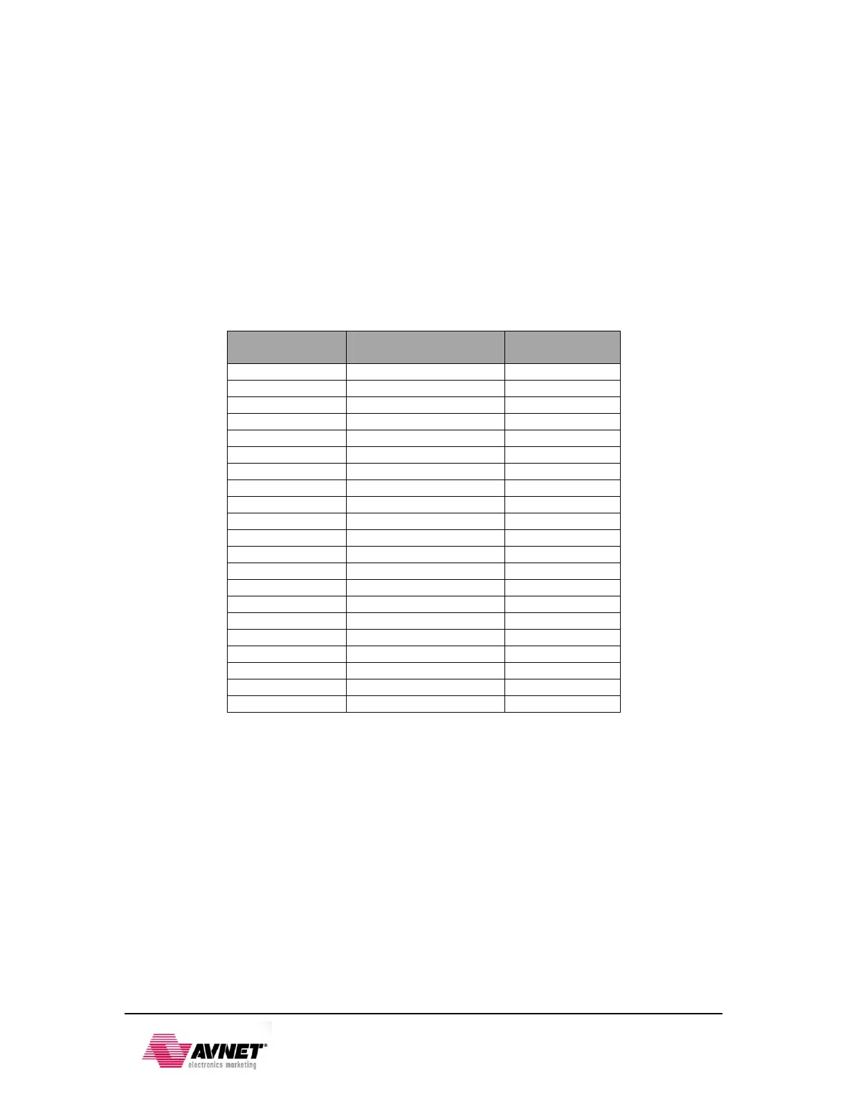
Table 7 – PS MIO User Interface
2.5.2 Available PL IO User Pins
PicoZed 7010/7020 provides 50 user PL IO pins from bank 34, 50 user PL IO pins from bank 35
of the Zynq-7000 AP SoC. Additionally, the PicoZed 7020 version provides access to 25 more
user PL IO pins from bank 13. The 100 PL IO pins on the PicoZed 7010 and the 125 PL IO pins
on the PicoZed 7020 connect to the Zynq Programmable Logic Sub-System for user
implementation of any feasible interface.
The PL IO pins were routed with matched lengths to each of the JX connectors. The matched
pairs, noted by “LVDS” in the net name of Tables 10, 11, and 12 may be used as either single
ended I/O or differential pairs depending on the end users design requirements.
Use of these signals for various interfaces depends on the bank voltages assigned. The end user
carrier card is responsible for providing VCCO for bank 34, bank 35, and bank13 depending on
what it being implemented and whether you are using PicoZed 7010 or PicoZed 7020.