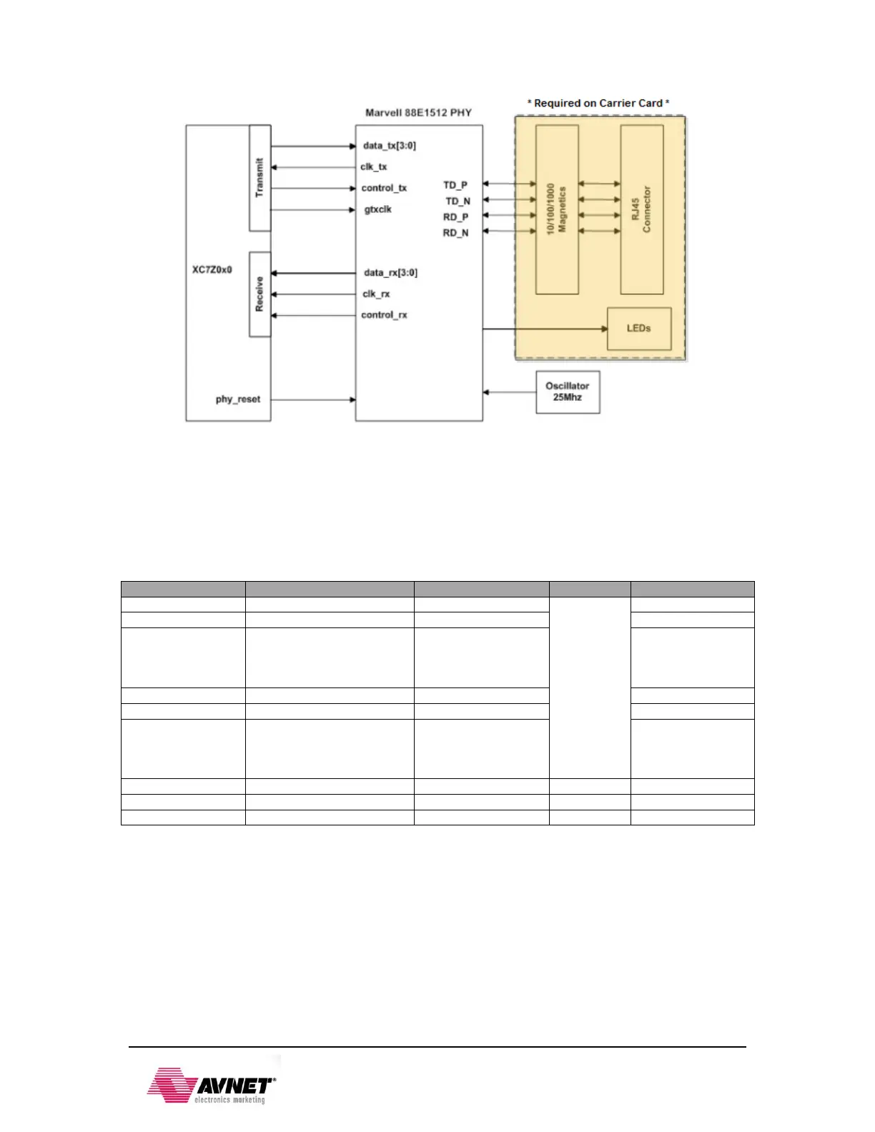
EasyManuals Logo

Avnet PicoZed 7010 User Manual

Default Icon
28 pages
To Next Page IconTo Next Page
To Previous Page IconTo Previous Page
Page #9 background imageLoading...
Page #9 background image
3-Feb-2015
8
Figure 3 10/100/1000 Ethernet Interface
Zynq requires a voltage reference for RGMII interfaces. Thus PS_MIO_VREF, E11, is tied to
0.9V, half the bank voltage of MIO Bank 1/501. The 0.9V is generated through a resistor divider.
The 88E1512 also requires a 25 MHz input clock. An ABRACON ASDMB-25.000MHZ-LC-T is
used as this reference.
Table 6 Ethernet PHY Pin Assignment and Definitions
Signal Name
Description
Zynq pin
MIO
88E1512 pin
RX_CLK
Receive Clock
B17
16:27
46
RX_CTRL
Receive Control
D13
43
RXD[3:0]
Receive Data
RXD0: D11
RXD1: A16
RXD2: F15
RXD3: A15
44
45
47
48
TX_CLK
Transmit Clock
A19
53
TX_CTRL
Transmit Control
F14
56
TXD[3:0]
Transmit Data
TXD0: E14
TXD1: B18
TXD2: D10
TXD3: A17
50
51
54
55
MDIO
Management Data
C11
53
8
MDC
Management Clock
C10
52
7
ETH_RST_N
PHY Reset
B14
47 **
16 **
** Requires a resistor change to the board to use PHY Reset. By default MIO47 is routed to JX3.
The datasheet for the Marvell 88E1512 is not available publicly. An NDA is required for this
information. Please contact your local Avnet or Marvell representative for assistance.

Questions and Answers:

Question and Answer IconNeed help?

Do you have a question about the Avnet PicoZed 7010 and is the answer not in the manual?

Avnet PicoZed 7010 Specifications

General IconGeneral
BrandAvnet
ModelPicoZed 7010
CategoryControl Unit
LanguageEnglish

Related product manuals