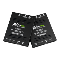
Indicator Troubleshooting
Lights on the
Receiver cont.:
LINK - Above RJ45 (HDBT) Port: (Green) This indicator shows that the AV HDBT link between the Transmitter and
Receiver is in tact. This light will ALWAYS be solid. If this light is flashing or not present do the following:
1. Check the length. The maximum distances are 40m (131ft) on 4K and 70m (230ft) on 1080P.
2. Remove any coils of cable and make sure that there is not excess cabling.
3. Bypass all patch panels and punch-down blocks.
4. Re-terminate connectors. Sometimes, even if a cable tester indicates the run is valid, something may be slightly off.
a. Standard RJ45 ends are recommended. Pass through style types can cause interference/crosstalk
5. Contact AVProEdge if these suggestions do not work.
STATUS- Above RJ45 (HDBT) Port: (Amber) This indicator shows that the power is present between the Transmitter and
Receiver. This light ALWAYS BLINKS steadily indicating everything is correct. If you do not see this light, try the
following:
1. Check the length. The maximum distances are 40m (131ft) on 4K and 70m (230ft) on 1080P.
2. Remove any coils of cable and make sure that there is not excess cabling.
3. Bypass all patch panels and punch-down blocks.
4. Re-terminate connectors. Sometimes, even if a cable tester indicates the run is valid, something may be slightly off.
a. Standard RJ45 ends are recommended. Pass through style types can cause interference/crosstalk
5. Try Powering from the Receiver instead of the Transmitter (See Receiver page for more about PoE direction).
6. Contact AVProEdge if these suggestions do not work.
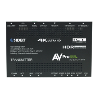
Functions & Setup
of the Receiver:
PoE Mode Slide Switch:
(On the back) This is used to select how you want to PoE is to be directed. There are two
options (you are choosing where the power is ORIGINATING from):
• TX = You will need to power the TRANSMITTER, the receiver will be powered over the CAT Cable (Default).
• RX = You will need to power the RECEIVER, the transmitter will be powered over the CAT Cable (This is called
"Reverse Power").
Using the Setting Button:
(On the back) The setting button can be pressed in different combinations based on what you
want to do. The status light on the front will flash based on your selection. The POWER LED is the idicator LED.
*Note: Only count the flashes, it will pause and then go solid.
Test Pattern Generator:
Press and hold the setting button (for 4 seconds) while powering up the
transmitter. The color bar pattern, as seen to the right will appear. When
in this mode, you can short press to toggle the resolution.
Quick press---Select the test pattern timing
• 1080P --- LED Flashes 1 Time
• 4K --- LED Flashes 2 Time
This is useful for checking cabling and for troubleshooting. It will check the link
between the Rx and the display/sink.
 Loading...