- 22 -
E
N
G
A
Preparation for fastening
B
Prepared cable pass-through channel
C
Hooks for attaching the bottom to the double bottom
D
Turret for locking the cover with 2.2 x 16 screw
E
Card centring guides
F
Turret for the locking the card to the bottom with 2.9 x 6.5 screw
G
Seats for the hooks for attaching to the bottom of the double
bottom
H
Hole prepared for the passage of the cable
(use the cable gland provided)
Installation tips
• Choose the position of the sensor carefully, keeping in mind that the sensor detects the intruder’s horizontal
movements and that the microwave detects movement towards and away from the sensor.
• Mount the sensor on a stable, vibration-free surface at a height between 1.9 and 2.2 metres.
• Do not aim the detector at fluorescent lamps.
• Do not expose the sensor to direct sunlight.
• Use shielded cable and connect the shield only to the negative of the controller and not the sensor.
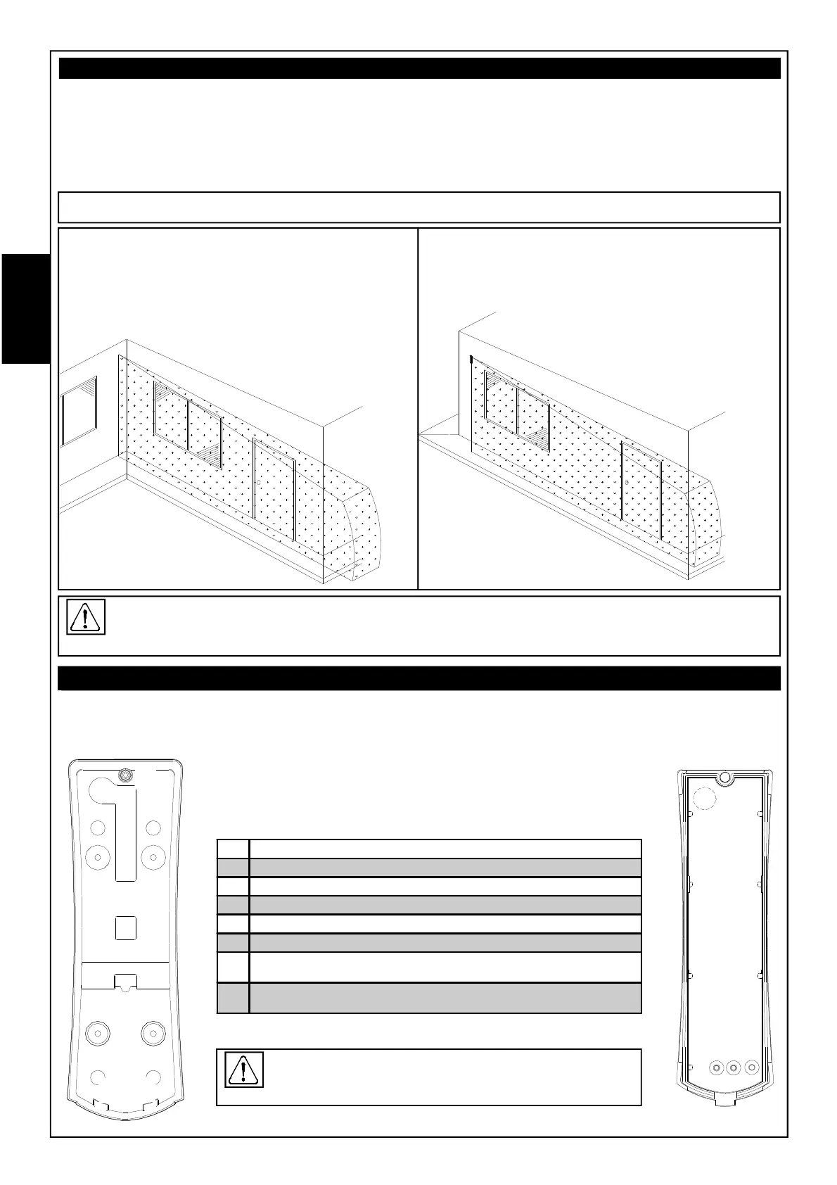
Installation examples:
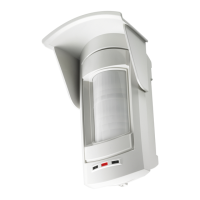
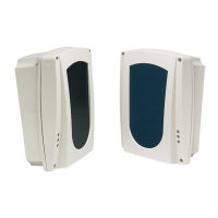
Basic sensor
The sensor has a double bottom for fastening to the wall or to the joint for tilting it 90°, to which the real
bottom that houses the card is then attached.
Double bottom
B
A A
A A
D
CC
E
G
G
F
H
Before performing the operations described below, be sure
to remove the electronic card from the base to avoid
damaging it.
Bottom
Wall installation:
To reach the best detection area (both in width and
depth), install the detector at least at 1 meter of the wall
to be protected; if the distance to the wall is less than 1
meter, use A or B accessory to orientate the sensor
+ 5° outwards (right or left as needed) so
that the innermost rays (wall side)
remain parallel to the wall.
90 ° bracket installation:
To reach the best detection area (both in width and depth),
in addition to C accessory which orientates the detector
90 ° to the wall to be protected, use the D
accessory to orientate the detector
+ 5 ° outwards so that the
innermost rays (side
wall) remain parallel to
the wall.
Often, in the presence of imperfections of the installation environment (not smooth and/or unstraight wall,
etc.), it is needed to orientate subsequently the detector outwards and/or down to compensate the defects
and to obtain a total detection area.