- 24 -
E
N
G
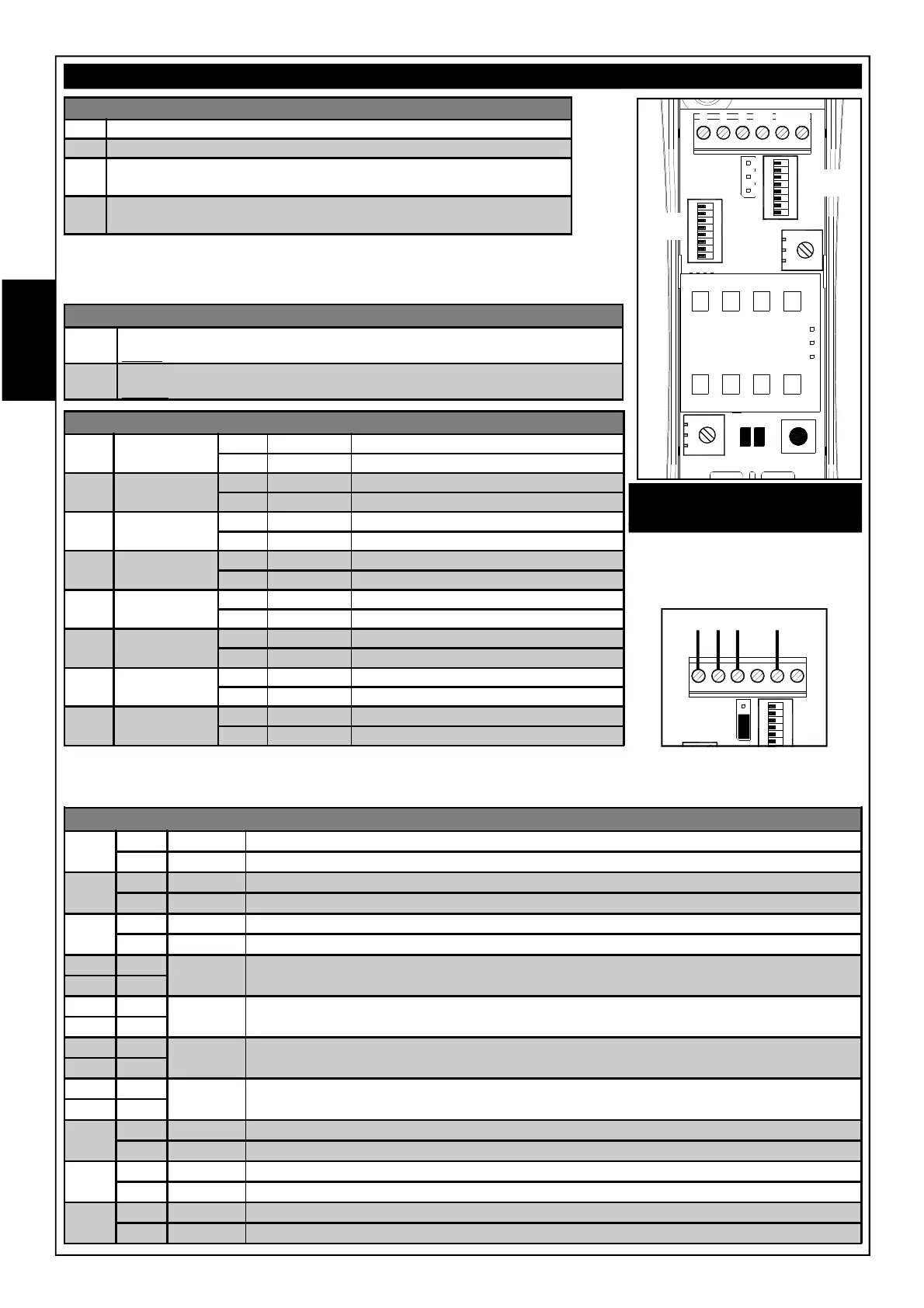
TERMINAL BLOCK
-
Power negative
+
12 V power positive =
C
Alarm contact of the sensor with capacity of 100 mA
Normally closed sensor idle
NC
T Anti-tampering contact of the sensor with capacity of 100 mA
Normally closed
T
SW1 - BALANCING RESISTANCES
DIP
1
TAMPER
(see S1)
ON
10 kohm resistance inserted
OFF DEFAULT
10 kohm resistance excluded
DIP
2
TAMPER
(see S1)
ON
5.6 kohm resistance inserted
OFF DEFAULT
5.6 kohm resistance excluded
DIP
3
TAMPER
(see S1)
ON
4.7 kohm resistance inserted
OFF DEFAULT
4.7 kohm resistance excluded
DIP
4
TAMPER
(see S1)
ON
2.2 kohm resistance inserted
OFF DEFAULT
2.2 kohm resistance excluded
DIP
5
ALARM
(in parallel)
ON
10 kohm resistance inserted
OFF DEFAULT
10 kohm resistance excluded
DIP
6
ALARM
(in parallel)
ON
5.6 kohm resistance inserted
OFF DEFAULT
5.6 kohm resistance excluded
DIP
7
ALARM
(in parallel)
ON
4.7 kohm resistance inserted
OFF DEFAULT
4.7 kohm resistance excluded
DIP
8
ALARM
(in parallel)
ON
2.2 kohm resistance inserted
OFF DEFAULT
2.2 kohm resistance excluded
S1 MANAGING THE TAMPER CONTACT
1 - 2
The resistance, configurable via DIP SWITCHES 1, 2, 3 and 4 of SW1, is in
series between the ALARM contact and that of the TAMPER (DEFAULT)
2 - 3
The resistance, configurable via DIP SWITCHES 1, 2, 3 and 4 of SW1, is in
parallel with the TAMPER contact
It is possible to insert balancing resistances for both the alarm and tamper contacts.
For the settings, refer to the tables for S1 and SW1.
SW2 - FUNCTIONS
DIP 1
ON DEFAULT
Led Enable
OFF
Led Excluded
DIP 2
ON Anti-mask active Tamper relay
OFF DEFAULT Anti-mask active Alarm relay
DIP 3
ON Anti-mask Microwave Active (Model OnE DT only)
OFF DEFAULT Anti-mask Microwave Disabled (Model OnE DT only)
DIP 4 OFF DEFAULT In this configuration the infrared has a default sensitivity (designed for classic use) and
performs a digital analysis of the signal.
DIP 5 OFF
DIP 4 ON LOW
In this configuration the infrared has a low sensitivity compared to the default and performs a
digital analysis of the signal that is stricter than the default and considers a double pulse
DIP 5 OFF
DIP 4 OFF MEDIA
In this configuration the infrared has a average sensitivity compared to the default and
performs a digital analysis of the signal that is stricter than the default
DIP 5 ON
DIP 4 ON HIGH In this configuration the infrared has high sensitivity and detects any signal by analyzing the
amplitude
DIP 5 ON
DIP 6
ON Yellow LED displays status of the Microwave (Model OnE DT only)
OFF DEFAULT Yellow LED displays status of the Anti-mask
DIP 7
ON Anti-mask Infrared Active
OFF DEFAULT Anti-mask Infrared Disabled
DIP 8
ON
Tamper Accelerometer enabled
OFF DEFAULT
Tamper Accelerometer excluded
OnE PA e OnE DT
ON
1 2 3 4 5 6 7 8
ON
1 2 3 4 5 6 7 8
SW1
SW2
S1
1
3
-
+
C NC
T1 T2
RV1
RV2
TAMPER
L1
L2
2
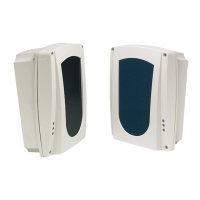
CONNECTIONS WITH S1 in
position 1 - 2
If a TAMPER resistance is inserted
in series using DIPs 1, 2, 3 and 4
of SW1, terminal blocks NC and
T2 must not be used
ON
1 2 3 4 5 6
x
x
-
+
L L
S1
NOTE: When you simultaneously set more than one of DIPs 1, 2, 3 and 4 (Tamper) to ON, the relative heating elements
will be placed in parallel with each other. The same principle applies to DIPs 5, 6, 7 and 8 (Alarm)