genius
ENGLISH
pag.11
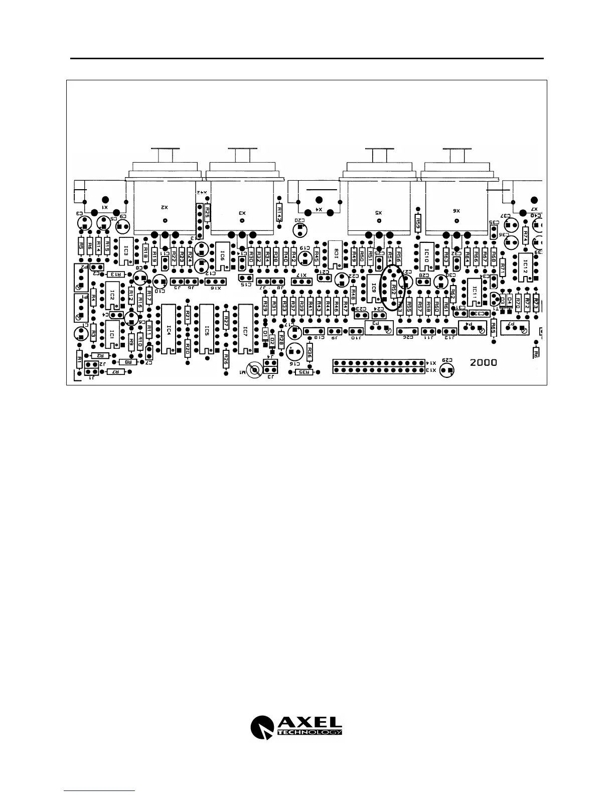
NOTE! Apart from closing Jumpers J10 e J12, to enable the 19 KHz tone when Input B is
selected You need to establish again the R52 resistor which is located near IC 9 and behind
the INPUT B – RIGHT XLR connector on the rear board.
4.8 OUTPUT LEVEL
J13 It enlarges by +6 dB the level of the Right channel output.
J14 It enlarges by +6 dB the level of the Left channel output.
4.9 PLUG AUTOFADER (OPTIONAL)
J30 master/slave A right
J31 master slave A left
J32 stereo coupling
4.10 JUMPER SUMMARY
J1 It sends the signal the Left channel of the A input to the Audio Detector adder .
J2 It sends the signal of the Right channel of the A input to the Audio Detector
adder.
J3 It sends the signal of the Left channel of the B input to the Audio Detector adder.
J4 It sends the signal of the Right channel of the B input to the Audio Detector
adder.
J5 A input Right channel SLAVE.
J5+J6 A input Right channel MASTER.
J5∩J6 A input Right channel INDEPENDENT.
J7 A input Left channel SLAVE.
J7+J8 A input Left channel MASTER.