genius
ENGLISH
pag.8
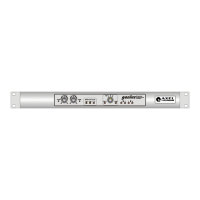
Æ B IN: Left and Right inputs on connectors 3 pole XLR female connectors electronically
balanced, PIN OUT standard configuration.
Ç OUT DRAW: PIN RCA unbalanced output, it supplies the same signal present in B IN ; we
suggest to use it as service output.
È A IN: Left and Right inputs on connectors 3 pole XLR female connectors electronically
balanced, PIN OUT standard configuration.
É OUT DRAW: PIN RCA unbalanced output, it supplies the same signal present in A IN; we
suggest to use it as service output.
4 JUMPER SETTING AND FUNCTIONS
4.1 INDEPENDENT, MASTER AND SLAVE
genius
can operate in INDIVIDUAL mode or in CHAIN, with several
genius
connected trough
an external BUS (see chapter 6).
The RDS, A left and A right signals can be withdrawn from their corresponding input
connectors placed on the back panel or from the External Bus connector.
This last solution is only used in the chain operative mode and distributes the signal on every
genius
without connecting them in parallel.
The A Left and A Right and RDS inputs have always to be set in one of the following ways:
• INDEPENDENT: it withdraws the signal form the input connector on the back panel and
ignores the one present on the Bus
• MASTER: it withdraws the signal form the input connector in the back panel and it injects it
in the Bus.
• SLAVE: it withdraws the signal form the Bus and ignore the one present on the input
connector.
Working with just 1
genius
the inputs must be set INDEPENDENT, while in chain you need to
distinguish between MASTER and SLAVE (and in the whole chain there must be just 1
equipment set as MASTER).
J5∩J6 A input Right channel INDEPENDENT.
J7∩J8 A input Left channel INDEPENDENT
J15∩J16 RDS input INDEPENDENT
J5+J6 A input Right channel MASTER.
J7+J8 A input Left channel MASTER.
J15+J16 RDS MASTER input.
J5 A input Right channel SLAVE.
J7 A input Left channel SLAVE.
J15 RDS input SLAVE.