genius
ENGLISH
pag.7
Å Led A R: it shows the presence of right A input in the right OUT output.
Æ Led B L: it shows the presence of left B input in the left OUT output.
Ç Led B R: it shows the presence of right B input in the right OUT output.
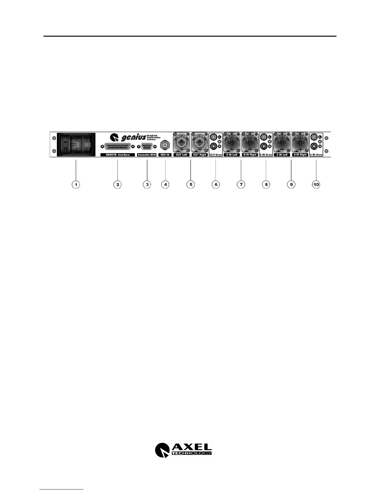
3.2 BACK PANEL
À ON/OFF switch: it switches on the equipment, the led inside shows the status of the
equipment. If the led is off and the switch is ON please check the power supply wire and
the PWS protection fuse integrity
VDE: net power supply standard plug ( using the provided net wire)
Fuse: the fuse box houses 2 fuses 100 mA T, the first one is connected in series to the
primary feed while the second one is stockpile. In case the primary feed is not 220/230 but
110/115 the fuse does not need to be replaced.
ATTENTION:
genius
is set ex-work at 220/230 VAC, if the network power supply is
110/115 VAC, you need to open the equipment and set the feed circuit tension modifier
placed behind the VDE plug.
Á Remote INTERFACE: interface 25 pole connector to input and output controls needed to
connect any external equipment controlling or to be controlled by
genius
.
 Expander BUS: 9 pole connector to connect in chain other
genius
, the BUS transfers
simultaneously signals and controls to all the equipment in the chain.
à RDS input: BNC connector which injects the RDS signal in the outputs, this connection is
used only when
genius
works in MPX split mode.
Ä OUT: Left and Right outputs on 3 pole XLR male connectors electronically balanced, PIN
OUT standard configuration (see chapter 7 for connections).
Å OUT DRAW: PIN RCA unbalanced output, it supplies the same signal present in OUT; we
suggest to use it only as service output.