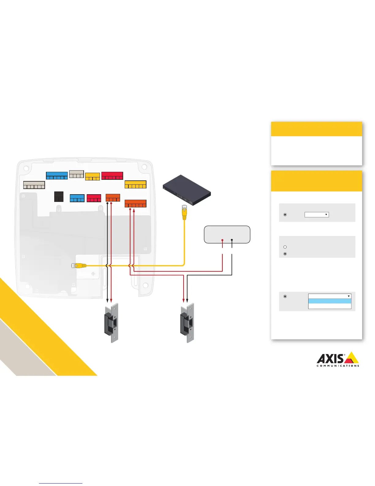
AXIS A1001 installation with
dual electric strikes
Voltage is determined by the power supply voltage out.
Adhere to local life safety code in all installations.
Ensure that your power supplies and relays are rated for the intended purposes.
Illustration does not depict cabling for reader, REX, Door monitor, battery backup and UPS.
AXIS Entry Manager
Programming
Application
1. Congure Lock 1 for 12 V and Fail-secure
3. Depending on your lock type, congure
Lock 2 Relay for
Relay open = Locked for a fail-secure lock
Relay open = Unlocked for a fail-safe lock
4. Wire the LOCK connector and the
RELAY|PWR connector according to
the drawing
2. Congure Lock 2 for Relay
>
Simple two-door solution with one door
using external power
Lock 1:
12 V
Relay
Relay open = Locked
Relay open = Locked
Relay open = Unlocked
Fail-secure
Lock 2:
12 V
Relay
READER I/O 1
DOOR IN 1 DOOR IN 2
LOCK
+MIC- +SPK-
AUDIO
AUX
A- B+ A- B+ D0 D1
A- B+ A- B+ D0 D1
-
12
V
IO
3
IO
4
IO
5
IO
6
READER DATA 1
READER DATA 2
DC IN
RELAY | PWR
*REL*- -
12
V
24
V
- H1 - H2
- IN1 - IN2 - IN3 - IN4
- +
- 3V
IO
1
IO
2
READER I/O 2
-
12
V
IO
7
IO
8
IO
9
IO
10
Lock 1 Lock 2
12 volt DC
Electric Strike
12/24 volt DC
Electric Strike
PoE Switch
Door Power Supply
12/24+
12/24-