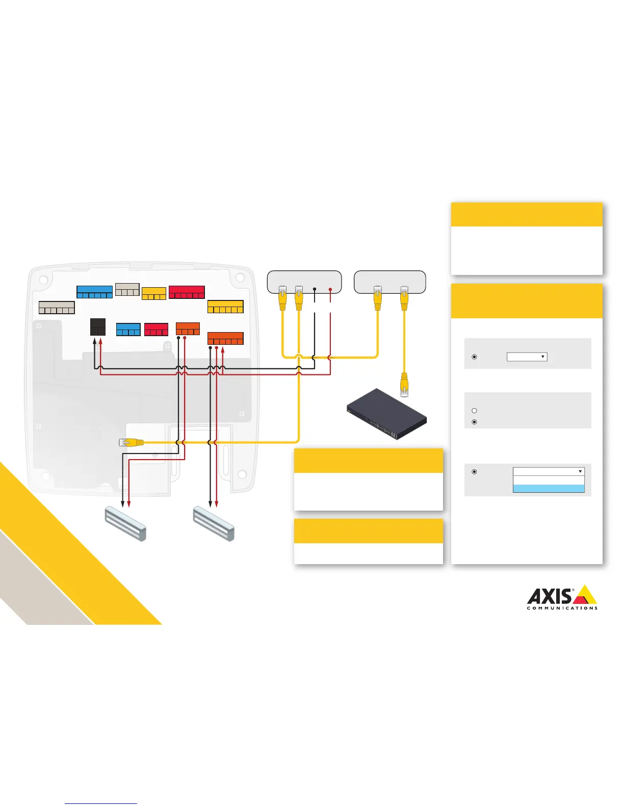
AXIS A1001 installation with
dual magnetic locks
Voltage is determined by the POE splitter voltage out.
Adhere to local life safety code in all installations.
Ensure that your power supplies and relays are rated for the intended purposes.
Illustration does not depict cabling for reader, REX, Door monitor, battery backup and UPS.
> AXIS T8127 60 W Splitter 12/24 V DC
High PoE Splitter
> AXIS T81B22 DC 30 W Midspan 1-port
> AXIS T8133 Midspan 30 W 1-port
> AXIS T8123-E Outdoor Midspan 30 W 1-port
30 Watt Midspan options
AXIS Entry Manager
Programming
Application
1. Congure Lock 1 for 12 V and Fail-safe
2. Congure Lock 2 for Relay
3. Congure Lock 2 Relay for
Relay open = Unlocked (fail-safe lock)
4. Wire the LOCK connector and the
RELAY|PWR connector according to
the drawing
>
Two-door solution with one 12 V lock and
one 12 or 24 V lock
Lock 1:
12 V
Relay
Relay open = Unlocked
Relay open = Locked
Relay open = Unlocked
Fail-safe
Lock 2:
12 V
Relay
READER I/O 1
DOOR IN 1 DOOR IN 2
LOCK
+MIC- +SPK-
AUDIO
AUX
A- B+ A- B+ D0 D1
A- B+ A- B+ D0 D1
-
12
V
IO
3
IO
4
IO
5
IO
6
READER DATA 1
READER DATA 2
DC IN
RELAY | PWR
*REL*- -
12
V
24
V
- H1 - H2
- IN1 - IN2 - IN3 - IN4
- +
- 3V
IO
1
IO
2
READER I/O 2
-
12
V
IO
7
IO
8
IO
9
IO
10
Data + Power Data
30 W Midspan
PoE IN Data OUT
Splitter
12/24 volt
Magnetic Lock
Lock 2
12 volt
Magnetic Lock
Lock 1
12/24-
12/24+
Switch