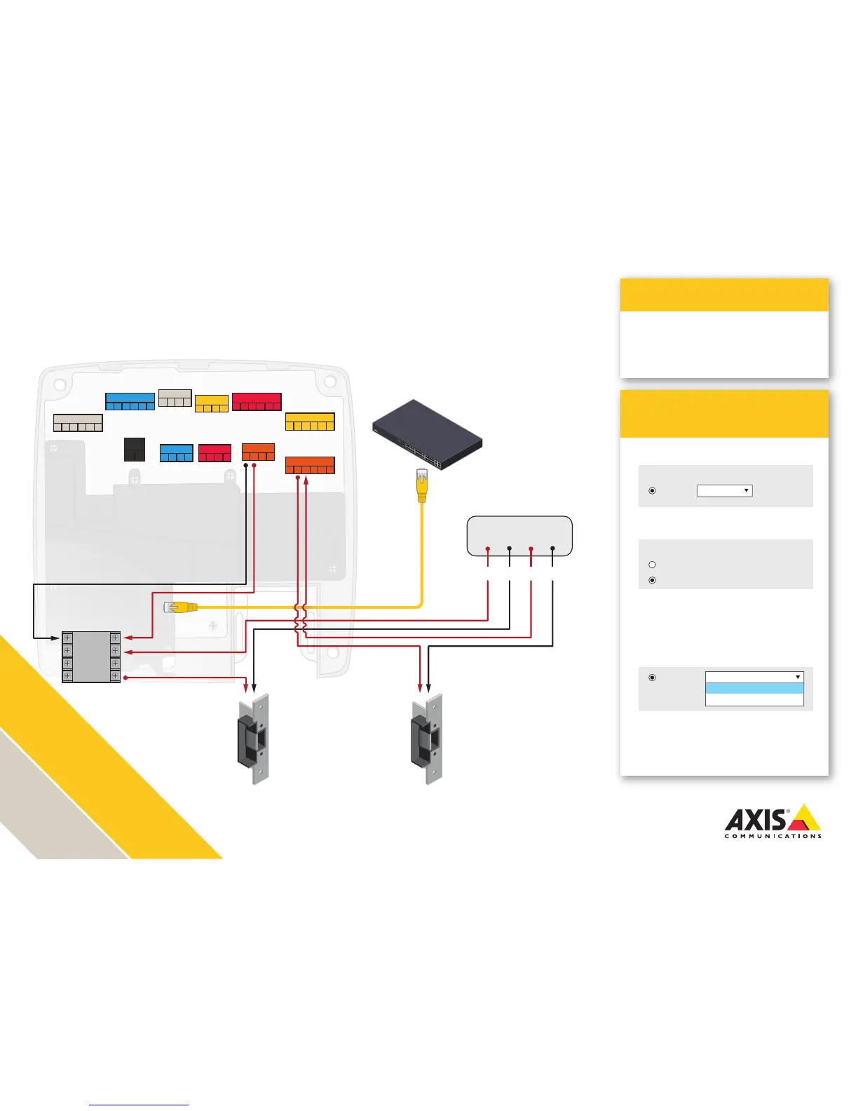
AXIS A1001 installation with dual
locks and external power supply
The AXIS A1001 lock output connects to the separate auxiliary
relay power input. 12/24 volts DC+ from a separate door power
supply connects to the C terminal of the slave relay. This transfers
to the NO terminal, pushing power to the lock.
Adhere to local life safety code in all installations.
Ensure that your power supplies and relays are rated for the intended purposes.
Illustration does not depict cabling for reader, REX, Door monitor, battery backup and UPS.
AXIS Entry Manager
Programming
Application
1. Congure Lock 1 for 12 V and Fail-secure
3. Depending on your lock type, congure
Lock 2 Relay for
Relay open = Locked for a fail-secure lock
Relay open = Unlocked for a fail-safe lock
4. Wire the LOCK connector and the
RELAY|PWR connector according to
the drawing
2. Congure Lock 2 for Relay
>
Two-door solution with high current locks
>
Suggested for use with existing power and
relay
Lock 1:
12 V
Relay
Relay open = Locked
Relay open = Locked
Relay open = Unlocked
Fail-secure
Lock 2:
12 V
Relay
READER I/O 1
DOOR IN 1 DOOR IN 2
LOCK
+MIC- +SPK-
AUDIO
AUX
A- B+ A- B+ D0 D1
A- B+ A- B+ D0 D1
-
12
V
IO
3
IO
4
IO
5
IO
6
READER DATA 1
READER DATA 2
DC IN
RELAY | PWR
*REL*- -
12
V
24
V
- H1 - H2
- IN1 - IN2 - IN3 - IN4
- +
- 3V
IO
1
IO
2
READER I/O 2
-
12
V
IO
7
IO
8
IO
9
IO
10
Relay
Lock 1 Lock 2
Electric Strike
12/24 volt DC12/24 volt DC
Electric Strike
Door Power Supply
12/24+
12/24-
12/24+
12/24-
POS+
C
NC
NO
NEG-
C
NC
NO
PoE Switch