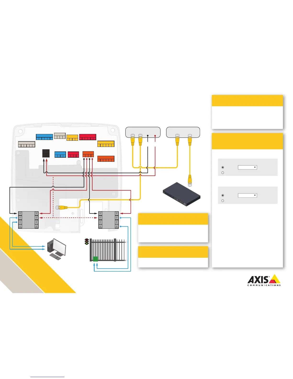
AXIS A1001 installation with
dual external auxiliary devices
Adhere to local life safety code in all installations.
Ensure that your power supplies and relays are rated for the intended purposes.
Illustration does not depict cabling for reader, REX, Door monitor, battery backup and UPS.
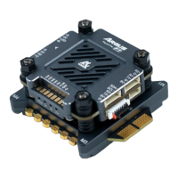
> AXIS T8127 60 W Splitter 12/24 V DC
High PoE Splitter
> AXIS T81B22 DC 30 W Midspan 1-port
> AXIS T8133 Midspan 30 W 1-port
> AXIS T8123-E Outdoor Midspan 30 W 1-port
30 Watt Midspan options
AXIS Entry Manager
Programming
Application
1. Congure Lock 1 for 12 V and Fail-secure
2. Congure Lock 2 for 12 V and Fail-secure
4. Wire the LOCK connector according to
the drawing
>
Solution for using relays to control devices
such as HVAC, gates, and other auxiliary
devices
Lock 1:
12 V
Relay
Fail-secure
Lock 2:
12 V
Relay
Fail-secure
READER I/O 1
DOOR IN 1 DOOR IN 2
LOCK
+MIC- +SPK-
AUDIO
AUX
A- B+ A- B+ D0 D1
A- B+ A- B+ D0 D1
-
12
V
IO
3
IO
4
IO
5
IO
6
READER DATA 1
READER DATA 2
DC IN
RELAY | PWR
*REL*- -
12
V
24
V
- H1 - H2
- IN1 - IN2 - IN3 - IN4
- +
- 3V
IO
1
IO
2
READER I/O 2
-
12
V
IO
7
IO
8
IO
9
IO
10
Data + Power Data
30 W Midspan
PoE IN Data OUT
Splitter
12/24-
12/24+
Energy Management
(add this wire for wet contact)
Switch
Relay
POS+
C
NC
NO
NEG-
C
NC
NO
Relay
POS+
C
NC
NO
NEG-
C
NC
NO