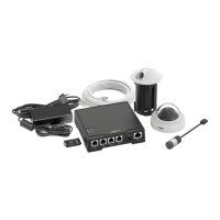
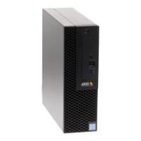
AXISF41MainUnit
PowerLEDIndication
Green
Normaloperation.
Amber
Flashesgreen/amberduring
rmwareupgrade.
ConnectorsandButtons
Forspecicationsandoperatingconditions,seepage14.
NetworkConnector
RJ45EthernetconnectorwithPoweroverEthernet(PoE).
NO NO
NO
TICE TICE
TICE
Theproductshallbeconnectedusingashieldednetworkcable
(STP).Allcablesconnectingtheproducttothenetworkshall
beintendedfortheirspecicuse.Makesurethatthenetwork
devicesareinstalledinaccordancewiththemanufacturer’s
instructions.Forinformationaboutregulatoryrequirements,see
ElectromagneticCompatibility(EMC)2.
I/OConnector
Usewithexternaldevicesincombinationwith,forexample,tampering
alarms,motiondetection,eventtriggering,timelapserecordingandalarm
notications.Inadditiontothe0VDCreferencepointandpower(DC
output),theI/Oconnectorprovidestheinterfaceto:
•Digitaloutput–Forconnectingexternaldevicessuchasrelays
andLEDs.ConnecteddevicescanbeactivatedbytheVAPIX®
ApplicationProgrammingInterface,outputbuttonsonthe
LiveViewpageorbyanActionRule.Theoutputwillshowas
active(shownunderSystemOptions>Ports&Devices)if
thealarmdeviceisactivated.
•Digitalinput–Analarminputforconnectingdevicesthat
cantogglebetweenanopenandclosedcircuit,forexample:
PIRs,door/windowcontacts,glassbreakdetectors,etc.When
12