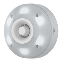
AXISF41MainUnit
Connectors
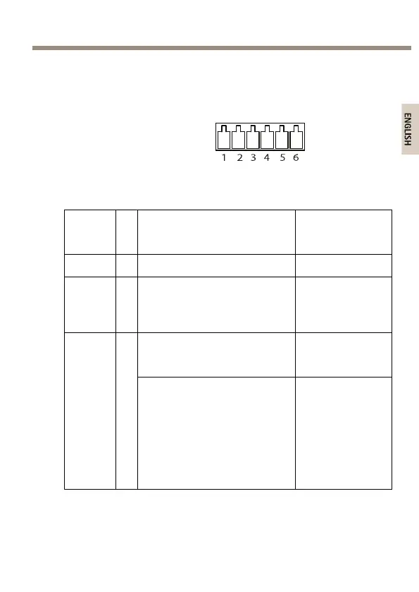
I/OConnector
6–pinterminalblock
Foranexamplediagram,seeConnectionDiagramsonpage18.
Func-
tion
P-
i-
n
Notes
Specications
0VDC(-)
1
0VDC
DC
output
2
Canbeusedtopowerauxiliary
equipment.
Note:Thispincanonlybeused
aspowerout.
12VDC
Maxload=50mA
Digitalinput–Connecttopin
1toactivate,orleaveoating
(unconnected)todeactivate.
0tomax30VDC Cong-
urable
(Inputor
Output)
3
–
6
Digitaloutput–Connected
topin1whenactivated,
oating(unconnected)when
deactivated.Ifusedwithan
inductiveload,e.g.arelay,
adiodemustbeconnected
inparallelwiththeload,for
protectionagainstvoltage
transients.
0tomax30VDC,
opendrain,
100mA
15