Foranexamplediagram,see.
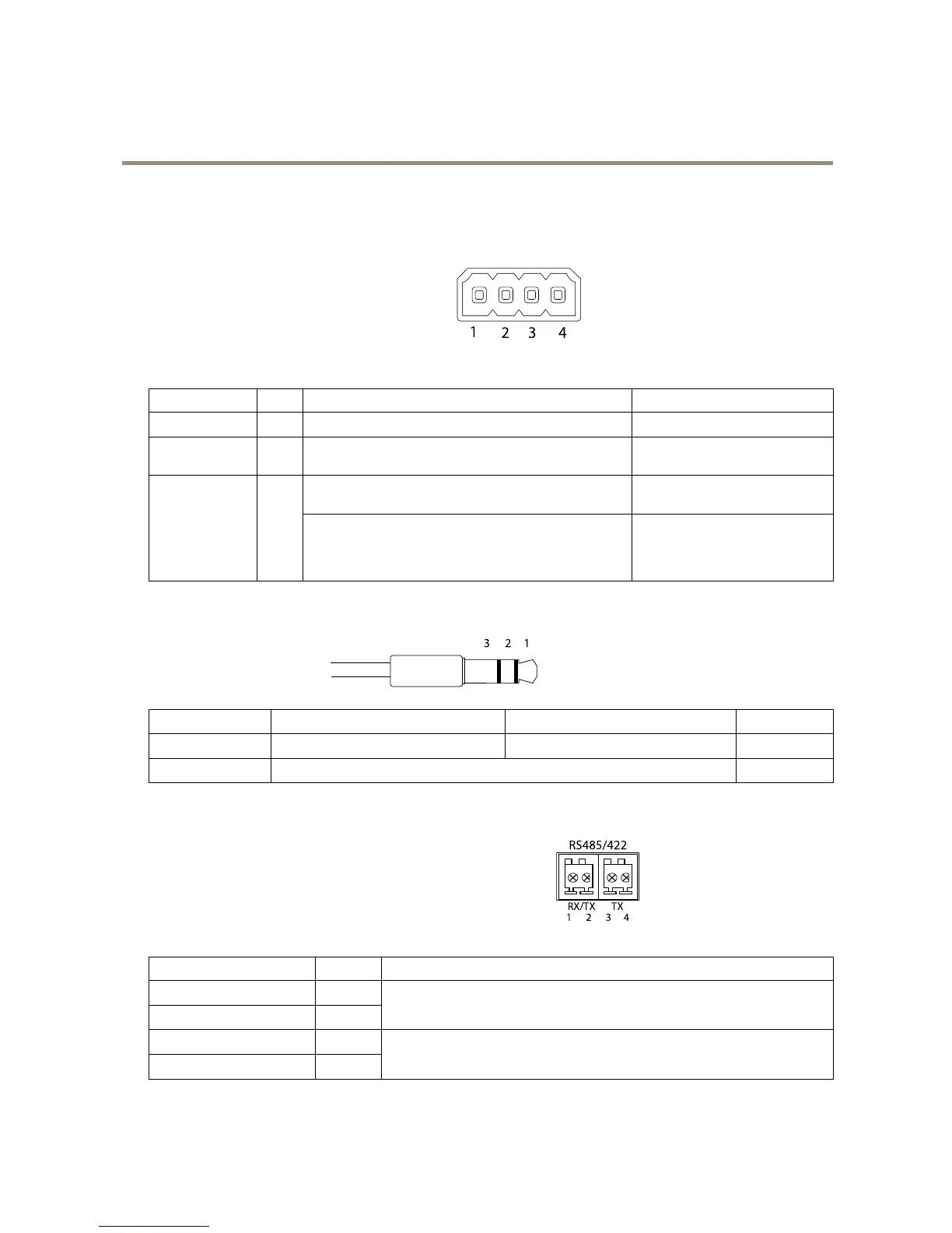
FunctionPinNotes
Specications
0VDC(-)
1
0VDC
DCoutput
2
Canbeusedtopowerauxiliaryequipment.
Note:Thispincanonlybeusedaspowerout.
12VDC
Maxload=50mA
Digitalinput–Connecttopin1toactivate,orleaveoating
(unconnected)todeactivate.
0tomax30VDC Congurable
(InputorOutput)
3–4
Digitaloutput–Connectedtopin1whenactivated,oating
(unconnected)whendeactivated.Ifusedwithaninductive
load,e.g.arelay,adiodemustbeconnectedinparallelwith
theload,forprotectionagainstvoltagetransients.
0tomax30VDC,opendrain,
100mA
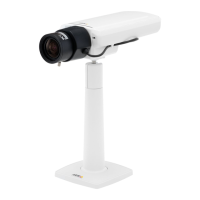
AudioConnector
3.5mmaudioconnectors
(stereo)
1Tip2Ring
3Sleeve
AudioInput
Microphone/Linein
Ground
AudioOutput
Lineout(mono)
Ground
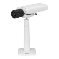
RS485/422Connector
Two2-pinterminalblocksforRS485/RS422serialinterface.Theserial
portcanbeconguredtosupport:
•Two-wireRS485halfduplex
•Four-wireRS485fullduplex
•Two-wireRS422simplex
•Four-wireRS422fullduplexpointtopointcommunication