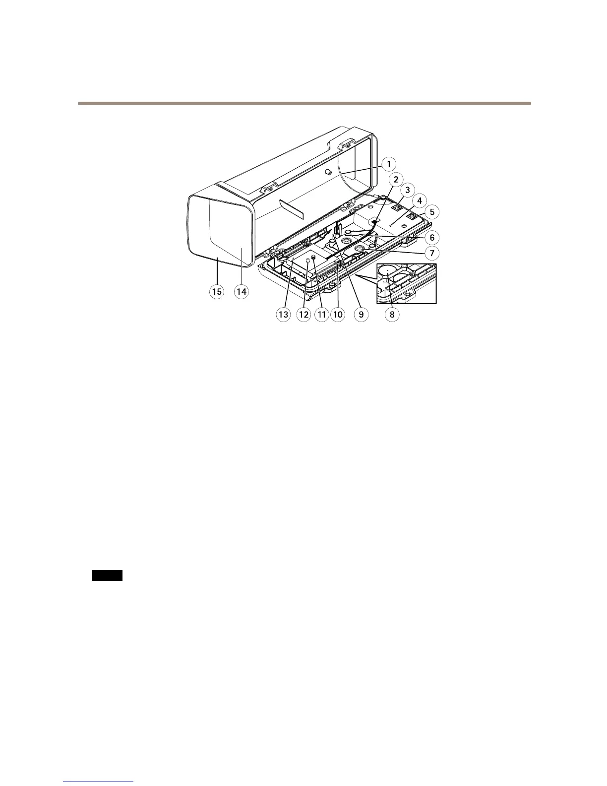
1
Safetywire
2
Heaterconnector
3
Networkconnector(PoEOUT)
4
StatusLEDindicator
5
Networkconnector(PoEIN)
6
Heatercable
7
CablegasketM20(2x)
8
Drill-out(2x)
9
Slotforintrusionalarmswitch–supportsAXISDoorSwitchA(soldseparately)
10
HolderscrewT20(2x)
11
CamerascrewT20
12
Pin
13
Holder
14
Window
15
Topcover
ConnectorsandButtons
Fortechnicalspecications,seepage68.
NetworkConnector
RJ45EthernetconnectorwithPoweroverEthernet(PoE).
NO NO
NO
TICE TICE
TICE
Theproductshallbeconnectedusingashieldednetworkcable(STP).Allcablesconnectingtheproducttothenetworkshall
beintendedfortheirspecicuse.Makesurethatthenetworkdevicesareinstalledinaccordancewiththemanufacturer’s
instructions.Forinformationaboutregulatoryrequirements,seeElectromagneticCompatibility(EMC)onpage2.
I/OConnector
Usewithexternaldevicesincombinationwith,forexample,tamperingalarms,motiondetection,eventtriggering,timelapserecording
andalarmnotications.Inadditiontothe0VDCreferencepointandpower(DCoutput),theI/Oconnectorprovidestheinterfaceto:
•Digitaloutput–ForconnectingexternaldevicessuchasrelaysandLEDs.Connecteddevicescanbeactivatedbythe
VAPIX®ApplicationProgrammingInterface,outputbuttonsontheLiveViewpageorbyanActionRule.Theoutputwill
showasactive(shownunderSystemOptions>Ports&Devices)ifthealarmdeviceisactivated.
8