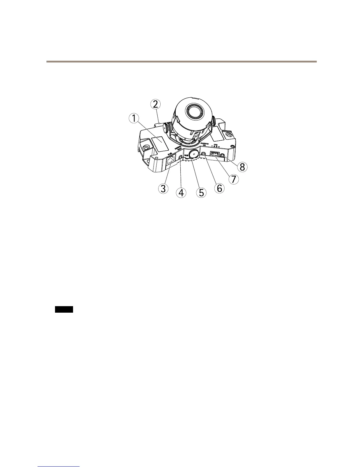
1
ProductIDandSerialnumber(S/N)
2
SDcardslot
3
Networkconnector(PoE)
4
Audioout
5
Network,StatusandPowerLEDindicators
6
Audioin
7
I/Oconnector
8
Controlbutton
ConnectorsandButtons
Fortechnicalspecications,seepage59.
NetworkConnector
RJ45Ethernetconnector.SupportsPoweroverEthernet(PoE).
NO NO
NO
TICE TICE
TICE
Theproductshallbeconnectedusingashieldednetworkcable(STP).Allcablesconnectingtheproducttothenetworkswitch
shallbeshielded(STP)andintendedfortheirspecicuse.Makesurethatthenetworkswitchisproperlygrounded.For
informationaboutregulatoryrequirements,seeRegulatoryInformationonpage2.
I/OConnector
Usewithexternaldevicesincombinationwith,forexample,tamperingalarms,motiondetection,eventtriggering,timelapserecording
andalarmnotications.Inadditiontothe0VDCreferencepointandpower(DCoutput),theI/Oconnectorprovidestheinterfaceto:
•Digitaloutput–ForconnectingexternaldevicessuchasrelaysandLEDs.Connecteddevicescanbeactivatedbythe
VAPIX®ApplicationProgrammingInterface,outputbuttonsontheLiveViewpageorbyanActionRule.Theoutputwill
showasactive(shownunderSystemOptions>Ports&Devices)ifthealarmdeviceisactivated.
•Digitalinput–Analarminputforconnectingdevicesthatcantogglebetweenanopenandclosedcircuit,forexample:
PIRs,door/windowcontacts,glassbreakdetectors,etc.Whenasignalisreceivedthestatechangesandtheinputbecomes
active(shownunderSystemOptions>Ports&Devices).
6