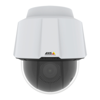
AXISP5512PTZDomeNetworkCamera
Multi-ConnectorCable(soldseparately)
Multi-ConnectorCable(soldseparately)
WhenconnectingexternalequipmenttotheAxisproduct,amulti-connectorcable(availablefromAxis)isrequiredinorderto
maintaintheproduct’sIPrating.Themulti-connectorcablecanbepurchasedfromyourAxisreseller.
Connectthemulti-connectorcabletotheproduct’smulti-connector.Tolocatethemulti-connector,seeHardwareOverview,onpage
6.Thecableprovidesthefollowingconnectors:
Powerconnector-3-pinterminalblockusedforpowerinput.Seeimagebelow.Usealimitedpowersource(LPS)witheitherarated
outputpowerlimitedto≤100Woraratedoutputcurrentlimitedto≤5A.
Audioin(pink)-3.5mminputforamonomicrophone,oraline-inmonosignal(leftchannelisusedfromastereosignal).
Audioout(green)-3.5mmoutputforaudio(linelevel)thatcanbeconnectedtoapublicaddress(PA)systemoranactivespeaker
withabuilt-inamplier.Astereoconnectormustbeusedfortheaudioout.
I/Oterminalconnector-Usewithexternaldevicesincombinationwith,forexample,tamperingalarms,motiondetection,event
triggering,timelapserecordingandalarmnotications.Inadditiontogroundandauxiliarypower,theI/Oterminalconnector
providestheinterfaceto:
•Digitaloutput—ForconnectingexternaldevicessuchasrelaysandLEDs.Connecteddevicescanbeactivatedbythe
VAPIX®ApplicationProgrammingInterface,outputbuttonsontheLiveViewpageorbyanActionRule.Theoutput
willshowasactive(shownunderSystemOptions>Port&Devices>PortStatus)ifthealarmdeviceisactivated.
•Digitalinput—Analarminputforconnectingdevicesthatcantogglebetweenanopenandclosedcircuit,for
example:PIRs,door/windowcontacts,glassbreakdetectors,etc.Whenasignalisreceivedthestatechangesand
theinputbecomesactive(shownunderSystemOptions>Port&Devices>PortStatus).
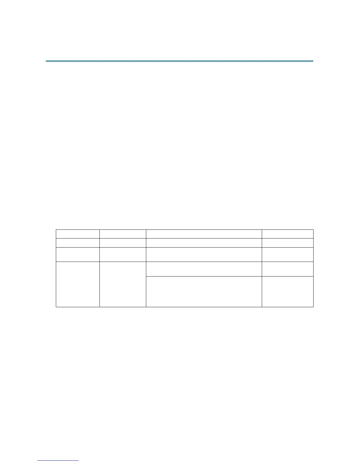
FunctionPinNotes
Specications
GND
1
Ground
3.3VDCPower
2
Canbeusedtopowerauxiliaryequipment.
Note:Thispincanonlybeusedaspowerout.
Maxload:
250mA
Digitalinput—ConnecttoGNDtoactivate,orleave
oating(unconnected)todeactivate.
0to+40VDC
Maxload:
100mA
Congurable(Input
orOutput)
3–6
Digitaloutput—Internalconnectiontogroundwhen
activated,oating(unconnected)whendeactivated.If
usedwithanexternalrelay,adiodemustbeconnected
inparallelwiththeload,forprotectionagainstvoltage
transients.
Maxvoltage:
+40VDC
53