Page 10 AXIS P5544 Installation Guide
• Digital input — An alarm input for connecting devices that can toggle between an open and
closed circuit, for example: PIRs, door/window contacts, glass break detectors, etc. When a
signal is received the state changes and the input becomes active (shown under System
Options > Port & Devices > Port Status).
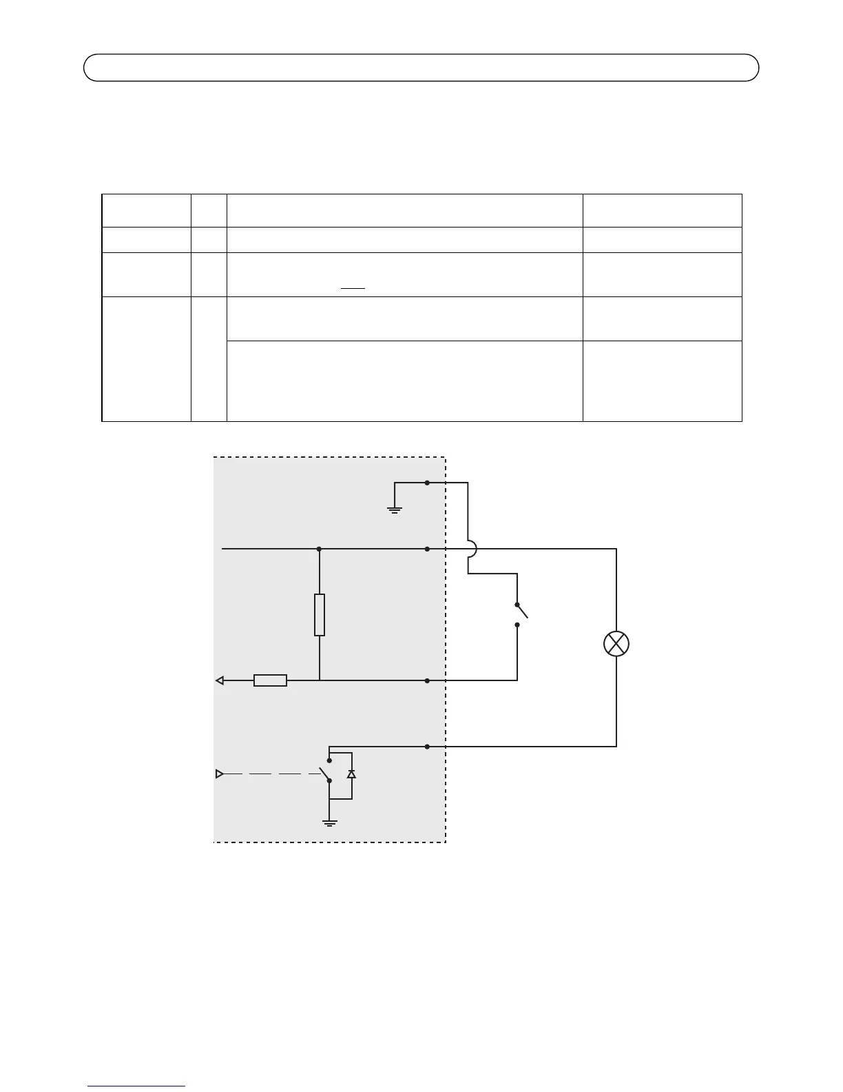
Function Pin Notes Specifications
GND 1 Ground
3.3 V DC
Power
2 Can be used to power auxiliary equipment.
Note: This pin can only
be used as power out.
Max. load = 250 mA
Configurable
(Input or
Output)
3-6 Digital input – Connect to GND to activate, or leave floating
(unconnected) to deactivate.
0 to +40 V DC
Digital output – Internal connection to ground when
activated, floating (unconnected) when deactivated. If used
with an external relay, a diode must be connected in parallel
with the load, for protection against voltage transients.
Max load = 100 mA
Max voltage = +40 V DC
3.3 V max 250 mA
1
2
A
B