34
AXIS P8221 - Unit connectors
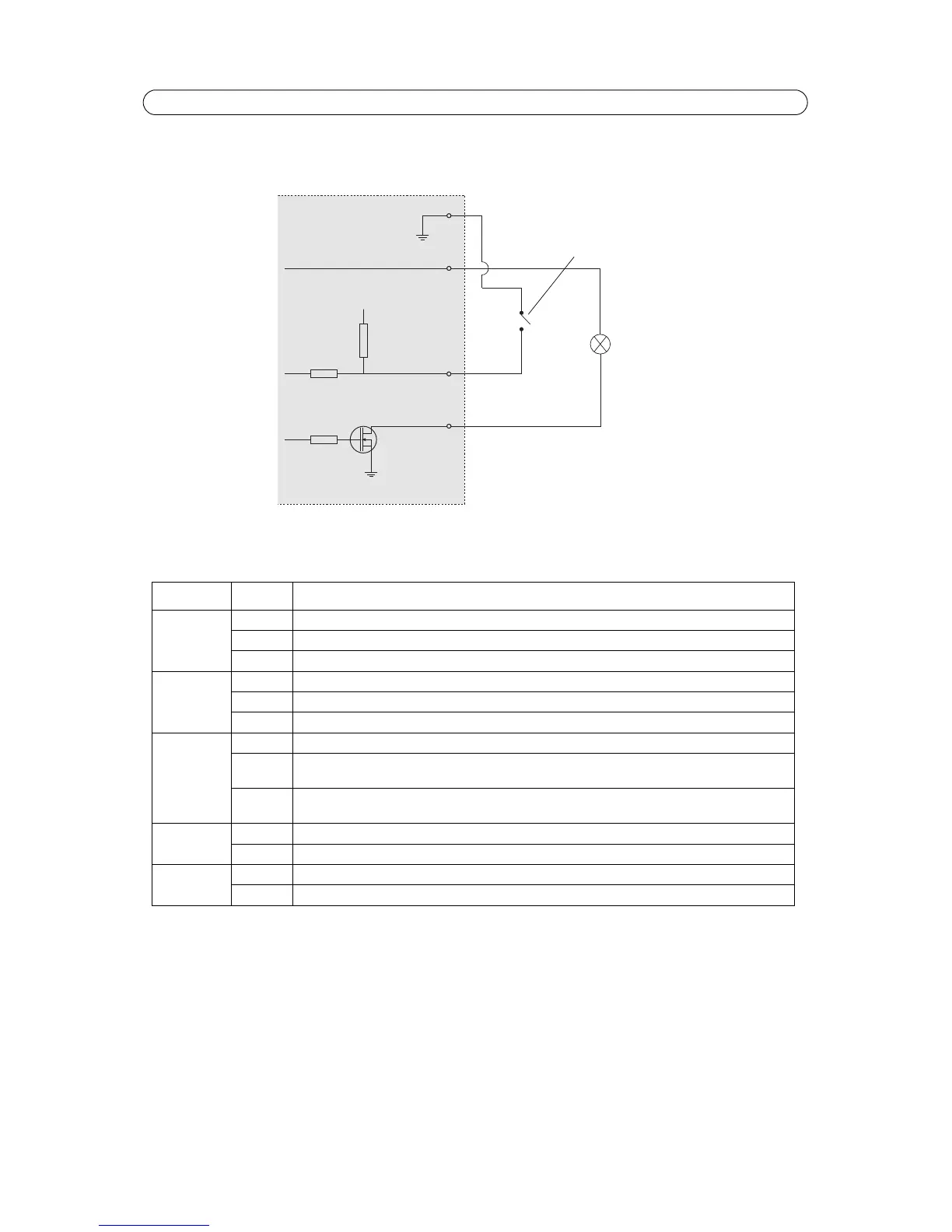
Connection diagram
The following connection diagram gives an example of how to connect an auxiliary device to the I/O terminal connectors.
LED indicators
Note:
The microphone level LED can be enabled and disabled from Setup > Audio > Audio Settings.
LED Color Indication
Mic level Green Microphone level signal between -20 dB and -3 dB
Amber Microphone level signal between -3 dB and -1 dB
Red Microphone level signal above -1 dB
Network Green Steady for connection to a 100 Mbit/s network. Flashes for network activity.
Amber Steady for connection to 10 Mbit/s network. Flashes for network activity.
Unlit No network connection.
Status Green Steady green for normal operation.
Amber Steady during startup, during reset to factory default or when restoring settings.
Flashes while waiting to record.
Red Flashes while recording audio clips.
Slow flash for failed upgrade.
Power Green Normal operation.
Amber Flashes green/amber during firmware upgrade.
Mic power Amber 48 V DC phantom power on
Unlit 48 V DC phantom power off