AXISQ1775NetworkCamera
Technicalspecifications
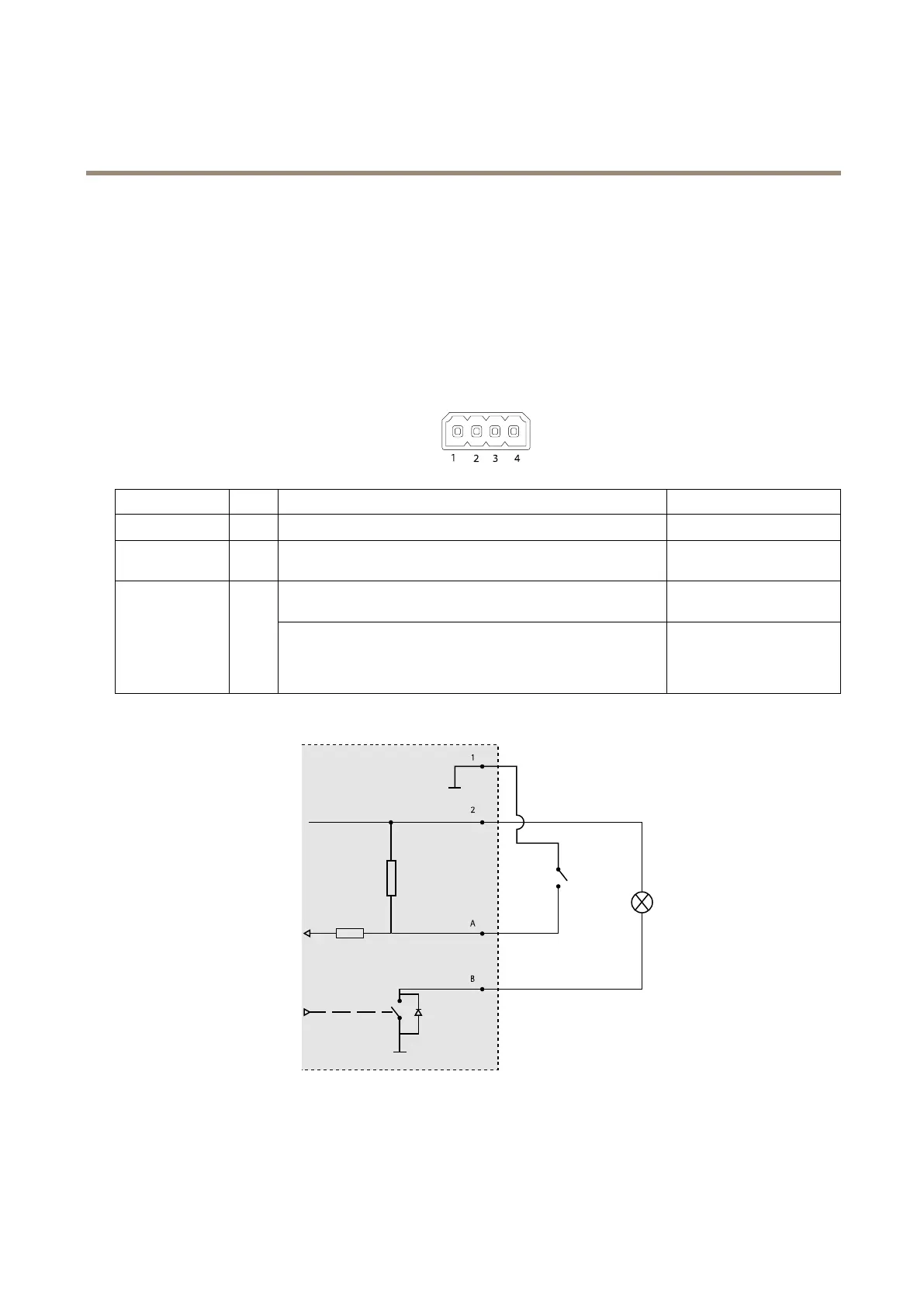
I/Oconnector
Usewithexternaldevicesincombinationwith,forexample,tamperingalarms,motiondetection,eventtriggering,andalarm
notications.Inadditiontothe0VDCreferencepointandpower(DCoutput),theI/Oconnectorprovidestheinterfaceto:
•Digitaloutput–ForconnectingexternaldevicessuchasrelaysandLEDs.Connecteddevicescanbeactivatedbythe
VAPIX®ApplicationProgrammingInterface,outputbuttonsontheLiveViewpageorbyanActionRule.Theoutputwill
showasactive(shownunderSystemOptions>Ports&Devices)ifthealarmdeviceisactivated.
•Digitalinput–Forconnectingdevicesthatcantogglebetweenanopenandclosedcircuit,forexample:PIRs,door/window
contacts,glassbreakdetectors,etc.Whenasignalisreceivedthestatechangesandtheinputbecomesactive(shown
underSystemOptions>Ports&Devices).
4–pinterminalblock
FunctionPinNotes
Specications
0VDC(-)
1
DCground0VDC
DCoutput
2
Canbeusedtopowerauxiliaryequipment.
Note:Thispincanonlybeusedaspowerout.
12VDC
Maxload=50mA
Digitalinput–Connecttopin1toactivate,orleaveoating
(unconnected)todeactivate.
0tomax30VDC Congurable
(InputorOutput)
3–4
Digitaloutput–Connectedtopin1whenactivated,oating
(unconnected)whendeactivated.Ifusedwithaninductiveload,e.g.
arelay,adiodemustbeconnectedinparallelwiththeload,for
protectionagainstvoltagetransients.
0tomax30VDC,opendrain,
100mA
1
0VDC(-)
2
DCoutput12V,max50mA
A
I/Oconguredasinput
B
I/Oconguredasoutput
69