AXIS Q60-S Series
1
2
3
4
5
6
7
8
9
10
12 11
1 8
2 7
9
3 6
4 5
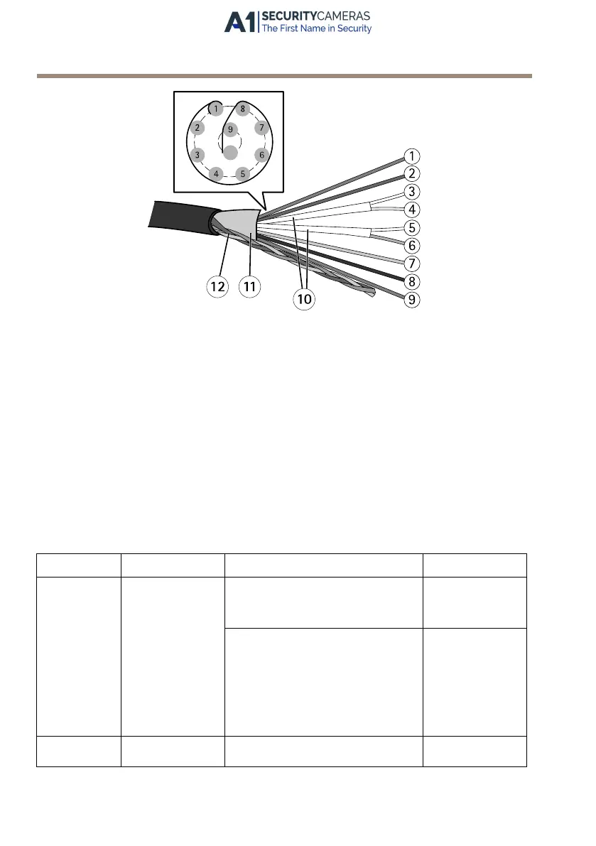
Multi-connector cable overview
1
Power wire (red)
2
Digital I/O wire (blue)
3
Ethernet wire (green/white)
4
Ethernet wire (green)
5
Ethernet wire (orange/white)
6
Ethernet wire (orange)
7
Digital I/O wire (yellow)
8
Ground wire (black)
9
Power wire (red)
10
Ethernet wire foil shield (2x)
11
Outer foil shield
12
Braided shield coil
Function Pin – wire Notes
Specications
Congurable
(Input or
Output)
2 – blue
7 – yellow
Digital input – Connect to pin
8 to activate, or leave oating
(unconnected) to deactivate.
0 to max 30 V DC
Digital output – Connected to
pin 1 when activated, oating
(unconnected) when deactivated. If
used with an inductive load, e.g. a
relay, a diode must be connected in
parallel with the load, for protection
against voltage transients.
0 to max 30 V DC,
open drain,
100 mA
RX+
3 – green/white
Ethernet – receiving
16
Available from A1 Security Cameras
www.a1securitycameras.com email: sales@a1securitycameras.com
 Loading...