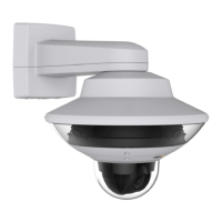
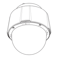
AXIS Q60-S Series
RX-
4 – green
Ethernet – receiving
TX+
5 – orange/white
Ethernet – transmitting
TX-
6 – orange
Ethernet – transmitting
0 V DC (-)
8 – black
0 V DC
DC output
(12 V)
1, 9 – red Used to power camera
12–13.2 V DC
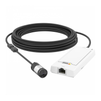
Media Converter Switch Connectors
For specications, see page 18.
NONO
NO
TICETICE
TICE
The product shall be connected using a shielded network cable (STP). All cables connecting
the product to the network shall be intended for their specic use. Make sure that the
network devices are installed in accordance with the manufacturer’s instructions. For
information about regulatory requirements, see Electromagnetic Compatibility (EMC) on
page 2.
Important
The media converter switch does not support hotswapping. Disconnect power from the
switch before swapping cameras. An attempt to hotswap could cause the switch to freeze,
in which case it must be restarted.
Power connector (DC input) - 2-pin terminal block for power input.
Power connector (DC output) - Two 2-pin terminal block for power output (pin 4 is not used).
Network connector RJ45 (external) - Two RJ45 connectors (10/100Base-T) for network
connectivity.
Network slot SFP (external) - Two SFP slots (100Base-FX/1000Base-X) for network connectivity.
Each RJ45 and SFP port has its own dip switch. The dip switches control how the port forwards
data. For more information, see the User Manual.
Dip switch position Description of use
Default (middle)
B When connecting to the network, directly or through a
router or network switch.
17
Available from A1 Security Cameras
www.a1securitycameras.com email: sales@a1securitycameras.com
 Loading...