WHITE
AXMINSTER
W
15
Identification and Description...
FREEPHONE 0800 371822
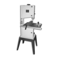
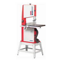
Main saw frame The main body of the machine that all the other parts are mounted upon.
(See fig 6)
Upper and lower The two doors that cover the upper and lower saw wheel compartments.
cover doors There are interlocks fitted to both doors so that the machine cannot
(See fig 6) operate if either door is left open.
Upper saw The upper saw wheel is mounted on double bearings on an axle that is
wheel mounted to a tilting plate. (To provide the fore and aft tilt movement that
(See fig 8) controls the blade tracking). The tilting plate is hinged to a base plate
that is mounted in slides in the upper saw wheel compartment.
(The base plate slides up and down allowing increasing or decreasing of
the blade tension). The saw wheel is fitted with a rubber tyre to give
better grip to the saw blade, and smoother running. It also allows the
blade to be tracked in the centre of the wheel; unlike the bad old days
when the blade had to be tracked off the front edge of the wheel to
safeguard the teeth.
Blade tensioning The blade tensioning wheel, at the top of the machine, is connected
wheel to a threaded rod that is engaged in the base plate of the upper saw
(See fig 8) wheel axle assembly. The threaded rod is anchored in the top of the saw
frame which allows the base frame to be driven up and down in its
mounting slides and tension or de-tension the blade.
Upper blade The upper blade guide assembly mounts the two side bearings and the
guide and rear thrust bearing that keep the blade stable (straight and untwisted)
guard above the table during the sawing operation. The guard is an integral
(See figs 6) part of the guide mounting leg to which the guide assembly is bolted so it
is always in place when the guide is raised or lowered to its working position.
Upper blade The upper blade guide height clamp is a butterfly nut and coach bolt
guide height arrangement that clamp through the guide mounting leg and the main
clamp saw frame. So, loose it will allow the mounting guide leg to be moved
(See figs 6 &12) up and down, tightened it will clamp the leg in position against the frame.
Saw table, tilt The saw table is mounted on the tilt quadrant, which is, in turn mounted
assembly in the quadrant housing and secured via a coach bolt and butterfly nut
and scale arrangement. Loosening the butterfly nut allows the table to be tilted up
(See fig 7 & 9) to 45 degrees clockwise. There is an adjustable bolt with a lock nut,
screwed into the underside of the table, which acts as a pre-set stop
when bringing the table back to the level position. There is a scale and
pointer attached to the rear of the quadrant and the housing to measure
the angle to which the table has been tilted. There are two slots machined
in the table to accept the slide of the mitre fence.



 To Next Page