WHITE
AXMINSTER
W
31
Setting the Fence...
Lower the upper blade guide to approximately 1 1/2"(38mm) above the table. Clamp in
place.
Loosen the cap head bolt holding the guide assembly in place (See Fig 13 A) and adjust the
back to front position so that the leading edges of the side guide bearings are
approximately 1.5 mm behind the gullets of the saw blade. Re-tighten the bolt. Loosen the
cap head bolt that clamps the rear thrust bearing in position (See Fig 14 C) and adjust the
thrust bearing to approximately 1mm behind the blade, re-tighten the bolt. Loosen the two
cap head bolts holding the guide bearings (See Fig 13 B) and move to approximately 0.5
mm from each side of the blade. Re-tighten the bolts. Gently push the blade back against
the thrust bearing (use a scrap of wood,) and check that the side bearings are still behind
the teeth of the blade.
Open the red safety cover (See Fig 15 D) by removing the front Phillips screw, loosen the
the two cap head bolts holding the lower blade guide assembly in place and position
similarly to the upper guide assembly. Re-tighten the bolts. Adjust the lower blade guides,
and set them similarly to the upper guides, (See Fig 15 B) using an allen key to release and
tighten the clamping bolts. When all adjustments have been made, recheck that when the
blade is pressed back against the thrust bearing, both the upper and lower side guides are
still behind the teeth of the saw replace the safety cover. When all adjustments are complete
replace the table insert. Re-connect the power, switch the saw on, allow to run for several
minutes, check that the blade is still tracking correctly, there is no excessive vibration, etc.
Switch off. The saw is ready to be used.
Setting the Blade Guides...
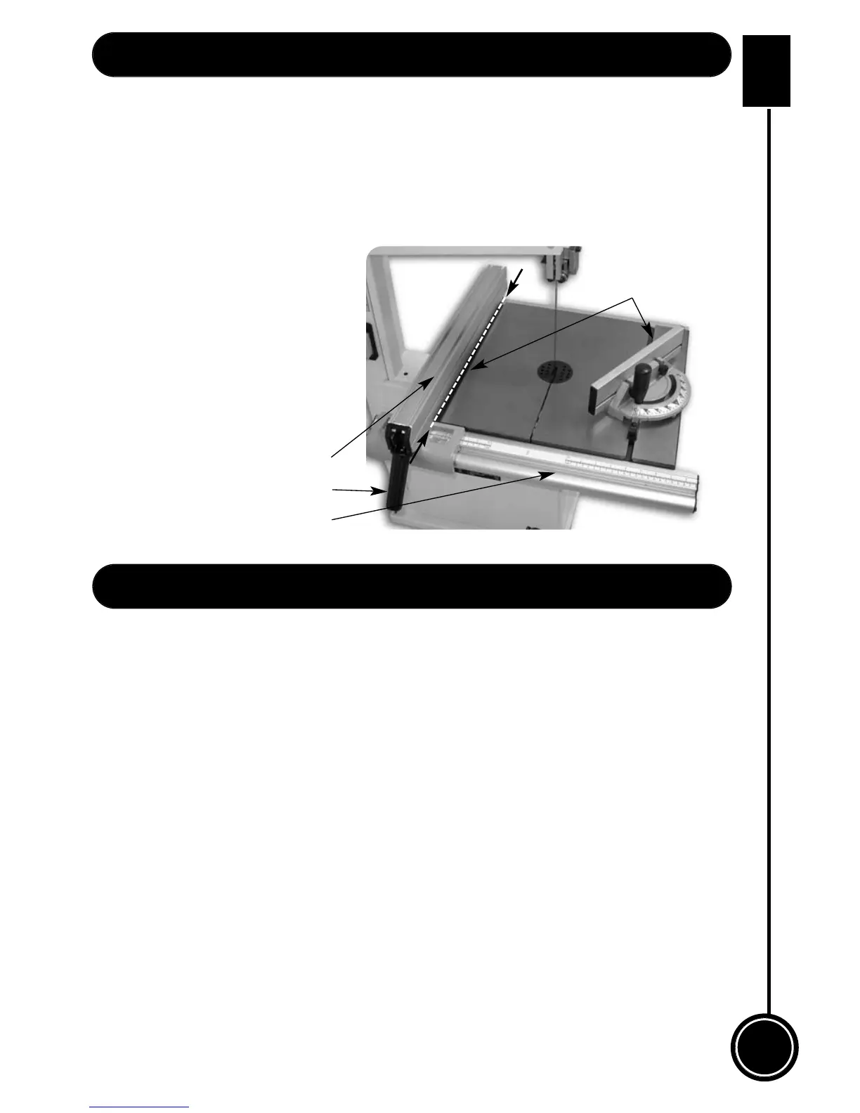
To make sure the guide fence is at 90˚line up the guide fence with the edge of the tables ‘T’
slot. If you find that the fence is out of alignment follow the steps below:
Note: It is recommended that you remove the extension fence to
make it easier to line the fence up.
• Clamp down the fence by pushing
the locking lever down.
• Loosen the 4 No. butterfly bolt that
secures the fence rail and adjust until
the fence is in alignment with the ‘T’
slot, then re-tighten the bolts.
• Replace the extension fence.
‘T’ slots
Fence
Locking lever
Fence rail



 To Next Page