Main Assembly
12
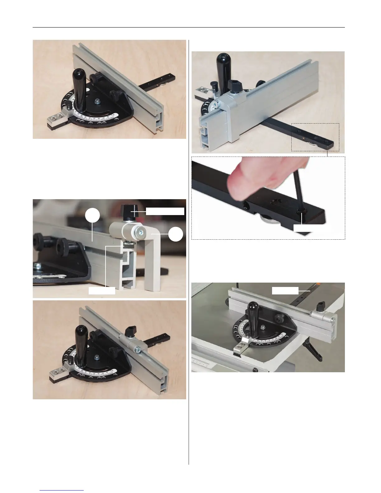
Step 5 Locate the depth stop assembly (g), loosen the butterfly
clamping knob on top of the unit. Line up the threaded ‘T’ bolt
with the ‘T’ slot to the top of the aluminium fence (f) and slide
on the assembly. Light tighten the butterfly knob to secure the
unit in position, see fig 34-35.
Fig 34-35
Step 6 Using the supplied Hex key (c) screw the two grub
screws (b) into threaded holes to the end of the steel bar, see
fig 36-37. The grub screws can be adjusted so the mitre fence
runs smoothly in the bandsaw tables ‘T’ Slot.
Fig 36-37
Step 7 Slide the mitre fence assembly into the cast iron table’s
‘T’ slot, adjust the aluminium fence (f) so it just misses the saw
blade, see fig 38.
Fig 38
g
f
‘T’ Slot ‘T’ Slot
Butterfly knob
Grub screw



 To Next Page