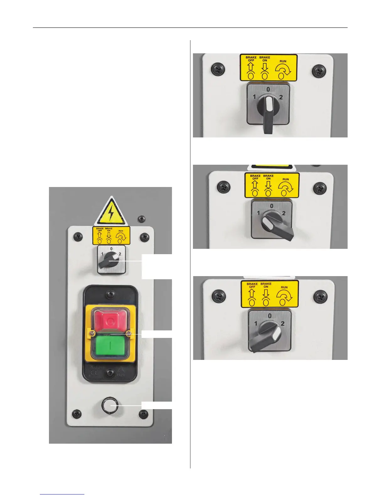
Electro-magnetic Motor Brake Switch
28
The electro-magnetic brake switch is located above the
NVR switch assembly and has three positions, see fig 83.
• Position (0) engages the motor brake to prevent
the bandsaw blade from moving and to isolate the
bandsaw to prevent it from being started accidentally,
see fig 84.
• Position (1) releases the motor brake allowing the
blade to turn freely for changing and for tracking
purposes, see fig 85.
• Position (2) is for running the machine. Move the
selector switch to this position the power indicator
will aluminate then press the ‘Green’ button on the
NVR switch to start the bandsaw, see fig 86.
Fig 83
NVR switch
Power indicator
Electo-magnetic
motor brake
switch
Fig 84
Fig 85
Fig 86



 To Next Page