DISCONNECT THE SAW
FROM THE MAINS SUPPLY!
Lower the upper blade guide to approximately
1 1/2”(38mm) above the table. Clamp in place.
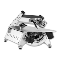
Loosen the nut (A) holding the guide assembly in
place and adjust thefore and aft position so that
the leading edges of the side guide bearings are
approximately 2mm behind the gullets of the saw
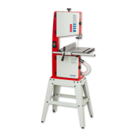
blade. Re-tighten the nut, see fig 16. Loosen the cap
head bolt that clamps the rear thrust bearing in
position (B) and adjust the thrust bearing to
approximately 1mm behind the blade, re-tighten
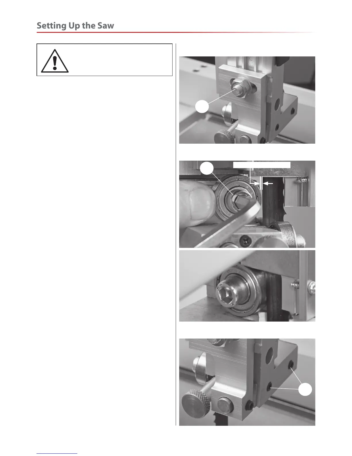
the bolt, (see fig 17). The blade should lineup with
the centre of the thrust bearing, if not loosen the
two grub screws (C) and move the upper blade
guide assembly in until correct, see fig 18. Retighten
the grub screws.
Loosen the two cap head bolts holding the guide
bearings (D) and move to approximately 0.5mm from
each side of the blade. NOTE: A five pound note is
approximately 0.5mm thick, slide a note between
the blade and guide bearing,turn the adjusting
knob (1), until the guide bearing is set to the correct
thickness. Re-tighten the bolts (D), see fig 19. Repeat
for the other guide bearing. Gently push the blade
back against the thrust bearing (use a scrap of wood,)
and check that the side bearings are still behind the
teeth of the blade.
Beneath the table, remove the safety guard and place
aside, loosen the two cap head nut holding the lower
blade guide assembly in place and position similarly
to the upper guide assembly, see fig 20. Re-tighten
the nut. Note: The guide bearing should always
be set behind the teeth of the saw.
Rotate the top wheel by hand, at this point. None
of the bearings should come into contact with the
blade-only when in use.
Adjust the lower blade guides, and set them similarly
to the upper guides, (D ) using an Hex key to release
and tighten the clamping bolts. When all adjustments
Setting the Blade Guides
Fig 16
A
Fig 17
B
2mm behind the blade
Fig 18
C