Remove the two Phillips screws
from either side of the switch
assembly, see fig 7, slide the
switch shroud over the switch,
see fig 7a and secure using the
two Phillips screws you removed
earlier.
Fitting NVR switch shroud
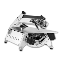
Fit the guide fence by clipping the rear clamp over
the back rail first and dropping the front clamp over
the fence rail, see fig 6 Push down on the lock lever,
and ensure the fence clamps up correctly.
see fig 6a.
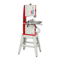
Check the guide fence is set parallel to the blade. Any
slight discrepancy can be taken out by loosening the
4 butterfly bolts that secure the blade of the guide
fence to the clamping body, adjust and re-tighten.
Larger discrepancies may require that the fence rail
is angled slightly.
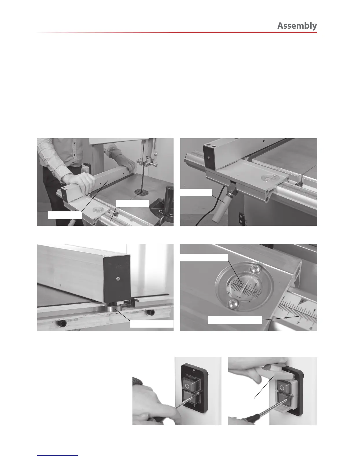
The dimensioning scales have adjustable index plates
set in the fence guide front clamp body to enable the
scales to be zero read, see fig 6c .
Fitting the guide fence
Fig 06 Fig 6a
Fig 6b Fig 6c
Fig 7
Fig 7a
Guide fence
Fence rail
Guide bearing
Dimensioning scale
Magnifying glass
Lock lever
Switch
shroud
 Loading...