80
•
PRINCIPLES OF OPERATION
Axopatch 200B, Copyright 1997-1999, Axon Instruments, Inc.
C1 = 1 pF
R
f
R
p
OPEN
CIRCUIT
10 V
p
FAST MAG
SLOW MAG
SLOW
FAST
+
I
p
C
p
V
p
I
C1
I
+
+
++
+
+
++
+
τ
+
-
τ
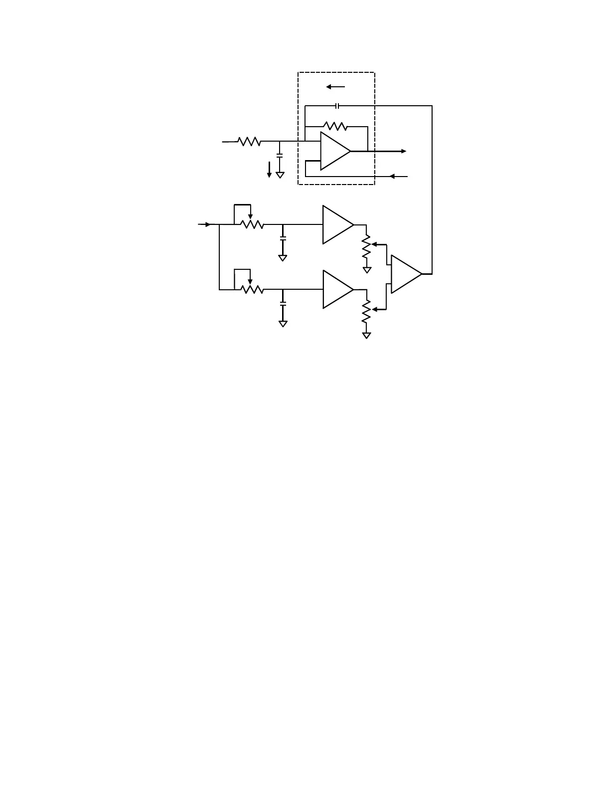
Figure 18.
Pipette capacitance compensation circuit.
When the pipette command potential (V
p
) changes, current I
p
flows into C
p
to
charge it to the new potential. If no compensation is used, I
p
is supplied by the
feedback element (R
f
) resulting in a large transient signal on the output (I).
By properly setting the fast and slow magnitude and τ controls, a current (I
C1
) can
be induced in capacitor C1 (connected to the headstage input) to exactly equal I
p
.
In this case no current needs be supplied by R
f
, and there is no transient on the
output.
The FAST controls compensate that part of C
p
that can be represented by a lumped
capacitance at the headstage input. This is the major part of C
p
. A small amount of
C
p
can only be represented as a capacitor with a series resistance component. This
takes longer to charge to its final value and is compensated by the SLOW controls.
 Loading...
