4
For non-amplified models ONLY:
• Cut the resistors off from the Green, Green/Black, Purple, and Purple/Black wires below the
heat shrink.
• Connect the Green wire to the left rear positive speaker output.
• Connect the Green/Black wire to the left rear negative speaker output.
• Connect the Purple wire to the right rear positive speaker output.
• Connect the Purple/Black wire to the right rear negative output.
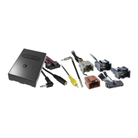
Note: The 4-pin to 4-pin resistor pad harness will not be used in this application.
Note: The relay attached to the GMOS-LAN-012 harness is only for audible turn signal clicks.
No extra steps are required to retain this feature, so leave the relay as-is.
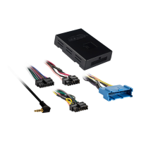
12-pin pre-wired ASWC-1 harness:
• This harness is to be used along with the optional ASWC-1 (not included) to retain steering
wheel controls. If the ASWC-1 is not being used, disregard this harness. If it will be used,
please refer to the ASWC-1 instructions for radio connections and programming. Disregard
the harness that comes with the ASWC-1.
DIN jack:
•
The DIN jack is to be used with the optional AX-LCD (sold separately) to retain satellite radio information
for models that do not retain this information in the driver’s information center. The AX-LCD can also be
used to view which factory sources are active; rear seat entertainment, satellite radio, AUX-IN
.
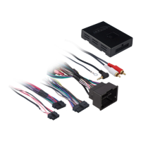
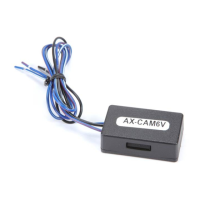
From the back-up camera harness to the aftermarket radio:
• If the vehicle comes equipped with a factory back-up camera, connect the Yellow RCA jack
to the aftermarket radios back-up camera video input.
• Activate the back-up camera video input on your radio if required.
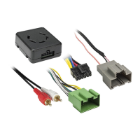
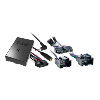
From the GMOS-LAN-012 harness:
• Connect the Black wire to the ground wire.
• Connect the Yellow wire to the battery wire.
• If installing either an ASWC-1 or AX-LCD (both sold separately), connect the (2) Red wires to
accessory power.
• The Black/Yellow wire is used for OnStar level adjustment for models that do not come
equipped with steering wheel controls. See OnStar Level Adjustment for further instructions.
• Connect the RCA jacks to the audio AUX-IN (if so equipped).
Note: This will only be required if you care to retain the factory AUX-IN, or satellite radio.
The following wiring is ONLY required if your vehicle DOES NOT come equipped with a
digital amplifier:
For analog amplified models ONLY:
• Connect the Green wire to the left rear positive speaker output.
• Connect the Green/Black wire to the left rear negative speaker output.
• Connect the Purple wire to the right rear positive speaker output.
• Connect the Purple/Black wire to the right rear negative output.
• Disconnect the 4-pin harness located between the 14-pin and 22-pin harness, and then
connect the supplied 4-pin to 4-pin resistor pad harness.
CONNECTIONS TO BE MADE (CONT.)
 Loading...