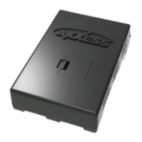
Do you have a question about the Axxess ASWC-1 and is the answer not in the manual?
Details specific green LED flash patterns and their corresponding wire connections for diagnostic feedback.
Details specific red LED flash patterns indicating auto-detected radio manufacturers.
Steps to prepare for remapping steering wheel control buttons, ensuring visibility of LED feedback.
Step-by-step instructions for assigning new functions to steering wheel control buttons using the ASWC-1.
Procedure to revert steering wheel control settings back to their original factory configuration.
Instructions for assigning a secondary function to steering wheel control buttons via long press.
Steps to erase a previously programmed dual assignment for a steering wheel control button.
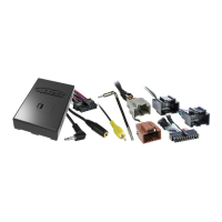
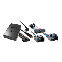
Guidance to diagnose and resolve issues when the ASWC-1 fails to auto-detect the vehicle or radio.
Step-by-step guide for programming the ASWC-1 when auto-detect fails or for specific custom configurations.
| Type | Steering Wheel Control Interface |
|---|---|
| Voltage | 12V DC |
| Compatibility | Compatible with most aftermarket radios and vehicles with steering wheel controls |
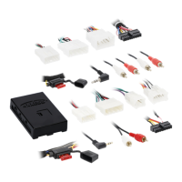
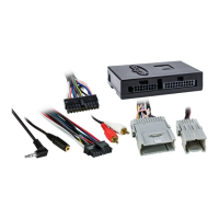
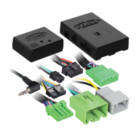
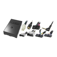
| Vehicle Integration | Connects aftermarket radio to factory steering wheel controls |
| Programming | Auto-detects vehicle and radio, customizable button assignments |
| Firmware Updates | Updatable via USB |
| Data Retention | Retains settings even after battery disconnection |
| Function | Allows control of aftermarket radio functions from the steering wheel |