EasyManua.ls Logo

Axxess AX-VL90032 User Manual

Axxess AX-VL90032
8 pages
To Next Page IconTo Next Page
Page #1 background imageLoading...
Page #1 background image
AX-VL90032
INSTALLATION INSTRUCTIONS
AxxessInterfaces.com © COPYRIGHT 2019 METRA ELECTRONICS CORPORATION REV. 7/25/19 INSTAX-VL90032
Product Info
INTERFACE FEATURES
INTERFACE COMPONENTS
TOOLS REQUIRED
• Wire cutter • Crimp tool • Solder gun • Tape
• Connectors (example: butt-connectors, bell
caps, etc.)
TABLE OF CONTENTS
Connections to be made .......................................2
Installing the AX-VL90032 interface .................3-4
Programming the ASWC-1 interface .....................5
Volvo XC90 Data Interface with SWC
2004-2014
Provides accessory power
Retains R.A.P. (retained accessory power)
Includes amplifier bypass harness
Provides NAV outputs (parking brake, reverse, speed sense)
Retains audio controls on the steering wheel
Retains balance and fade
Micro “B” USB updatable
AX-VL90032 interface
ASWC-1 interface
AX-VL90032 harness
ASWC-1 harness
Female 3.5mm connector with stripped leads
Question and Answer IconNeed help?

Do you have a question about the Axxess AX-VL90032 and is the answer not in the manual?

Axxess AX-VL90032 Specifications

General IconGeneral
BrandAxxess
ModelAX-VL90032
CategoryAutomobile Accessories
LanguageEnglish

Summary

Volvo XC90 Data Interface with SWC 2004-2014

Interface Features

Lists key interface capabilities like accessory power, R.A.P. retention, NAV outputs, and USB updatability.

Interface Components

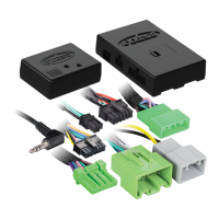
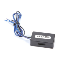
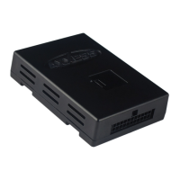
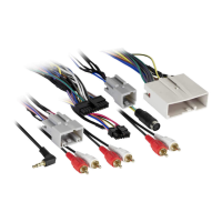
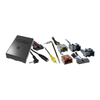
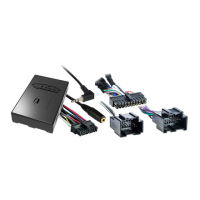
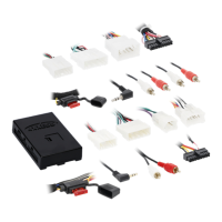
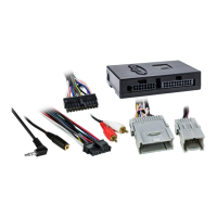
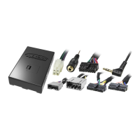
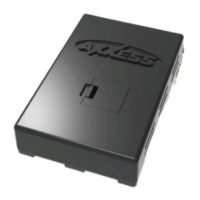
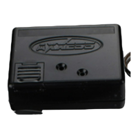
Lists the physical parts included in the AX-VL90032 kit.

Tools Required

Lists the necessary tools for performing the installation.

Connections to be Made

AX-VL90032 Harness Wiring

Details wire-to-wire connections for the AX-VL90032 harness to the aftermarket radio.

ASWC-1 Harness Wiring

Details wire connections for the ASWC-1 harness to the aftermarket radio for steering wheel controls.

Installing the AX-VL90032 Interface

Amplifier and Radio Connections

Describes connecting the interface to the factory amplifier and radio display connectors.

Advanced Installation Steps

Double DIN Radio Installation Procedure

Outlines steps for disassembling the dash and relocating the factory display for double DIN radios.

Programming the ASWC-1 Interface

Understanding LED Feedback

Explains how to interpret the ASWC-1's LED signals to identify connected radio brands.

ASWC-1 LED Feedback Legend

Provides a reference table mapping specific LED flash counts to radio manufacturers.

Technical Support and Resources

Contact Information and Hours

Provides contact phone number, email, and operating hours for technical support.

Related product manuals