9-6
Chapter 9 Maintenance and Inspection
Assembling the Probe
Basically, assemble the probe in the reverse order of disassembly.
When assembling the probe, be sure to check the O-ring and matching surface for
scratches and contamination. If the O-ring or matching surface is dirty, wipe it off using
a clean cloth and apply a thin layer of silicone grease. If the O-ring or matching surface is
scratched, replace it with a new one.
y
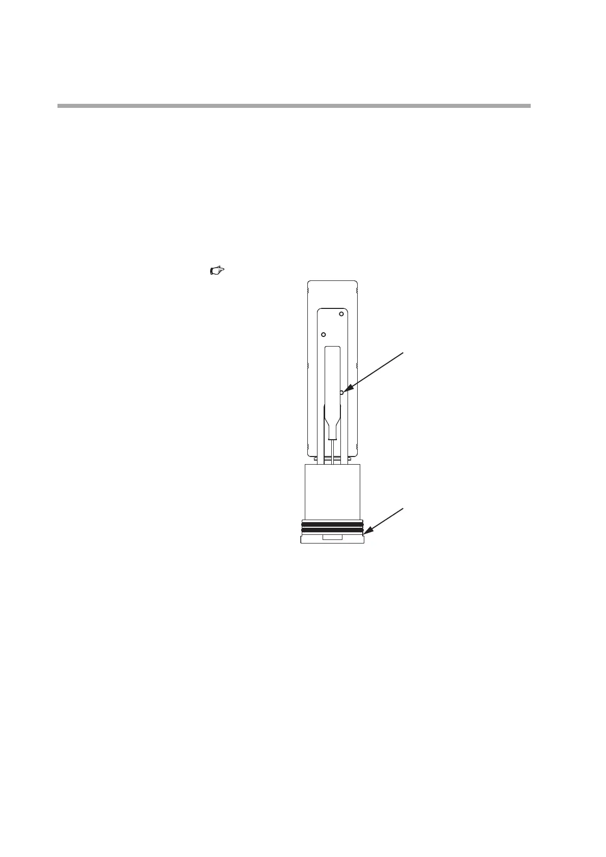
Assembling the Meterbody and Housing
(1) Put the meterbody in the housing and push it until its rim comes in contact with the
housing. At this time, make sure that the seal cap stands upright, and does not droop
down.
(
Fig. 9-8)
Fig. 9-8. Orientation of seal cap
(2) Screw in the cover until the O-ring attached to the housing is completely hidden.
y
Assembling the Cable
(1) Insert the connector attached to the ends of the lead wires into the connector inside
the probe.
(2) Put the lead wires inside the probe. Position the wires so that they will not get caught
when they are pulled out the next time.
(3) Push in the shell until the flange comes in contact with the housing.
(4) Screw in the cover until the O-ring attached to the housing is completely hidden.
(5) To test for airtightness, follow the steps below.
(1) Apply a pressure of 50 to 100 kPa* from the pipe at the end of the hollow cable on the
junction box side.
(2) Submerge the entire probe in water and check that no air bubbles are found.
* If excessive pressure is applied accidentally, the sensor may break. The maximum pressure to be
applied from the hollow cable is 100 kPa.
Seal cap
Meterbody rim
 Loading...