Azbil Corporation
Model: AMT, HDT - CV3000 Series Control Valves
26
Assembly Procedure
Before assembly, check the parts for scrapes, damage, deformation, peeling off of
paint, and other abnormality. To assemble the actuator, proceed as followes:
(a) Direct Action Type
(1) Fix the bottom diaphragm case and yoke with the bolts. (For models HA2D
and HA3D, install the diaphragm case and spring plate together.)
(2) Install the springs on the spring plate. The quantities of springs are as
follwes;
HA2 ....................4 springs
HA3, HA4 ........... 8 springs
Except particular models as follows:
HA2, 38 mm stroke,
80 - 240 kPa (0.8 - 2.4 kgf/cm
2
) ....... Total 8 springs (with double springs)
HA3, 50 mm stroke,
80 - 240 kpa (0.8 - 2.4 kgycm
2
) ........ Total 16 springs (with double springs)
HA4, 75 mm stroke,
80 - 240 kPa (0.8 - 2.4 kgf/cm
2
) ....... Total l6 springs (with double springs)
(3) Insert the actuator rod (to which the diaphragm is connected) into the
bushing, exercising are not to damage the bushing inside surface or dust
seal with the threaded section of the rod. (For example, cover the threaded
section with adhesive tape to prevent damaging the hushing.) Set the stopper
in parallel with the yoke.
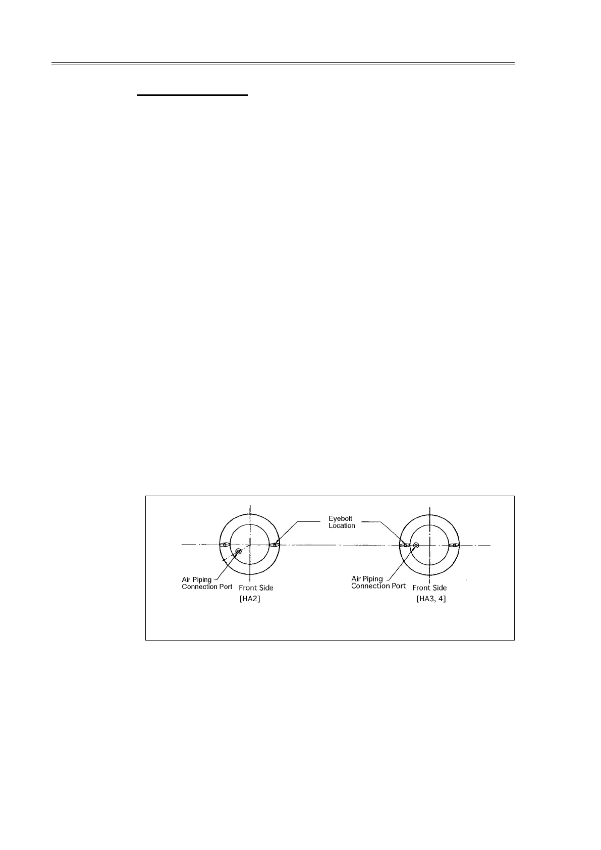
(4) Place the top diaphragm case and fix it with the pair of eyebolts.
Notes: • Set the air piping connection port in the location shown in the
illustration. (Fig. 4-16)
• Tighten the pair of eyebolts uniformly by tightening them
alternately. The initial setting of the springs is complete by
tightening of these eyebolts.
Fig. 4-16 Direct Action Type
(5) Clamp the diaphragm case with other clamping-bolts than the pair of eyebolts.
(6) Install the pointer, secure the lock nut, and install the stem connector. (Connect
the air pipe to the air piping connection port of the top diaphragm case.)
(7) After the assembly is complete as above, check the following.
1. Applying an air pressure of 490 kPa (5kgf/cm
2
) via the air piping
connection port of the top diaphragm case, check the diaphragm periphery
for air leak by using soapsuds.
2. Check that the actuator smoothly operates for its full stroke.
Note: Check this operation by operating the actuator as an independent unit.