Azbil Corporation
Model: AMT, HDT - CV3000 Series Control Valves
2
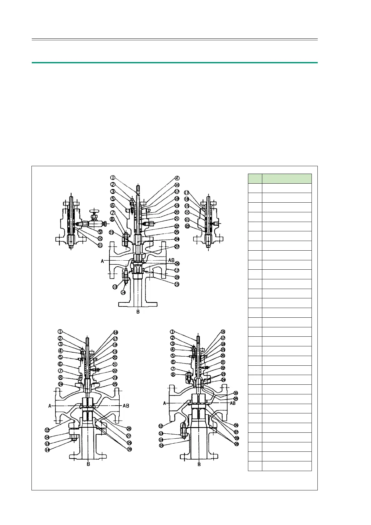
1.3 Structures
The structures of typical CV3000 Series control valves are shown is Fig. 1-1 and 1-2.
The valve body is connected to the bonnet with stud bolts and nuts. Gaskets are
provided at the connection section to seal against the internal fluid or to let the valve
body make up a pressure vessel. The valve plug is supported by the guide ring and
cage, and driven by the actuator. The actuator has multiple springs and a diaphragm,
and converts the pneumatic control signal into a mechanical (positional) control
signal with which to position the valve plug.
In the illustrations, for mixing service, the left and bottom ports are inlets and the
right port is outlet. For diverting service, the right port is inlet.
1” Size Valve Body
1-1/2” and 2” Size Valve Body Valve Body 2-1/2” or More
No. Parts Name
1 Valve Stem
2 Stud Bolt
3 Nut
4 Packing Flange
5 Yoke Lock Nut
6 Bonnet
7 Stud Bolt
8 Nut
9 Lubricator
10 Lantern Ring
11 Packing
12 Valve Body
13 Nut
14 Stud Bolt
15 Tail Piece
16 Packing Follower
17 V-Packing Holder
18 V-PTFE Packing
19 V-Packing Retainer
20 V-Packing Spring
21 Blind Plug
22 Packing Ring
23 Gasket
24 Pin
25 Guide Bushing
26 Seat Ring
27 Valve Plug
28 Gasket
29 Seating Guide
30 Guide Ring
Fig. 1-1 Mixing Type Three-way Valve (AMT)