Chapter 3. WIRING
10
Checking of wiring n
Before applying the voltage to this unit, check that the wiring is correct.
Procedures ●
(1) Remove the cover by unscrewing the four (4) mounting screws that secure it to
the AUD300C1000.
Remove 2 tube unit retaining screws on the rear of the tube unit.
Hold the rear of the tube unit and gently raise it upward to remove it.
(2) Turn ON the power to the burner controller.
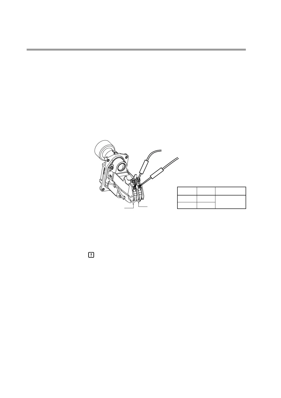
(3) Measure the DC voltage between the F-terminal and G-terminal with a multi-
meter or digital voltmeter.
(4) Connect the positive probe to the G-terminal (yellow lead wire) and the nega-
tive probe to the F-terminal (blue lead wire).
Positive probe (red)
Negative probe (black)
F-terminal
blue lead wire
G-terminal
yellow lead wire
Terminal Probe Voltage
F −
160 to 220 Vdc
G +
>> If a voltage of 160 Vdc to 220 Vdc is output, it is determined that the wiring
work has been performed correctly. If the measured DC voltage is a negative
value, the wiring to the F-terminal and G-terminal is connected reversely.
(5) Next, measure the DC voltage between the shutter voltage S1-terminal and S2-
terminal (both are white lead wires).
Handling Precautions
The polarities of the S1-terminal and S2-terminal are not specified. When •
measuring the voltage with an analog multi-meter, set a large voltage
range so that the indication needle does not deflect over the negative
scale to check the polarities. After that, measure the shutter voltage.
>> If the indication needle swings in a range of 15 Vdc to 24 Vdc, it is determined
that the wiring is connected correctly.*
If the indication needle of the multi-meter shows 24 Vdc constantly or if it
shows 0 V, the wiring may be incorrect.
* If a flame exists, the shutter voltage swings within a range of 0 Vdc to 24 Vdc.
(6) Mount the tube unit 1 min. or longer after the power to the burner controller
has been turned OFF.
(7) Attach the cover to the AUD300C, and secure it with the 4 mounting screws.
 Loading...