9
WARNING
Before removing, mounting, or wiring the AUD300C, be sure to turn off the AUD300C and all con-
nected devices. Failure to do so might cause electric shock.
When measuring the voltage between the F-terminal and G-terminal of this unit in the wiring check,
do not touch any terminal by bare hand.
Doing so may cause an electric shock.
CAUTION
Only authorized personnel who have the technical skill about the combustion equipment and flame
safeguard control must carry out the mounting, wiring, inspection, adjustment, and maintenance
work.
Always separate the signal cables of this unit from the high voltage cables of the ignition transformer
and power cables, and then always run the signal cables in a different conduit tube.
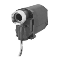
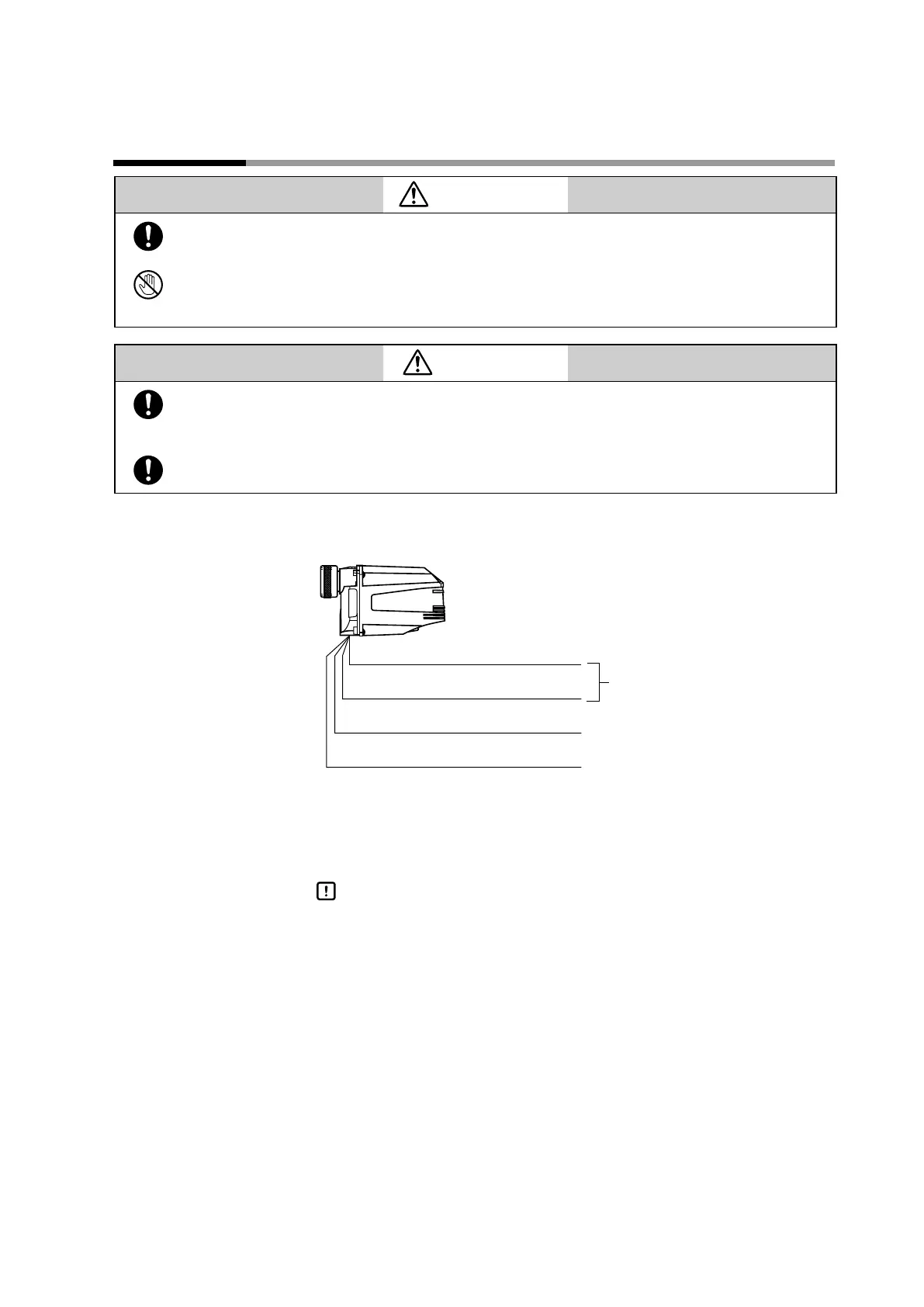
Wiring diagram n
White
Shutter output
terminal
White
Yellow
(G)
(F)
Blue
AUD300C
When performing the wiring work, put all lead wires used for the connection with
the burner controller in the conduit tube or conduit box. Additionally, run these
lead wires with they separated from other power cables.
Handling Precautions
Never run the lead wires to this unit in the same conduit tube contain-•
ing the high voltage cables, such as power cables or ignition transformer
cables.
Put the high voltage cables of the ignition transformer and the ground-•
ing cables in the same conduit tube. At the same time, ground one end
of this conduit tube firmly. In particular, this caution must be observed
strictly when using an automotive spark plug.
If the surge of the ignition transformer adversely affects this unit, ground •
both ends of the conduit tube between this unit and combustion safety
control unit or change the cable running route.
Chapter 3. WIRING
 Loading...