WARNING
Before removing, mounting, or wiring the AUD300C, be sure to turn off the AUD300C and all con-
nected devices. Failure to do so might cause electric shock.
Do not touch the AUD300C or the F or G terminals of the burner controller immediately after the
power to the burner controller has been turned OFF.
The F and G terminals are still electrically alive for 1 minute after the power has been turned OFF,
causing an electric shock hazard.
CAUTION
Only authorized personnel who have the technical skill about the combustion equipment and flame
safeguard control must carry out the mounting, wiring, inspection, adjustment, and maintenance
work.
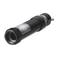
Tools and parts to be prepared ●
• AnalogflamemeterFSP136A100
• Fordetailsaboutreplacementparts,
●Maintenance parts and optional parts (on page 2).
Trouble checking procedures ●
(1)Checktheoperatingconditions.
Check item Contents
Power voltage • Check that the power switch is turned ON correctly.
• Check for loose power terminal.
• Check that the voltage is within the allowable range.
Wiring • Check that the terminal No. is correct.
• Check for faulty wiring.
• Check the insulation for deterioration or damage.
Ambient temperature • Check that the temperature is +100 °C or less.
(up to 120 °C during flame detection)
Ambient humidity • Check that the ambient humidity is 90 %RH or less.
• Check that no dew condensation occurs inside the unit.
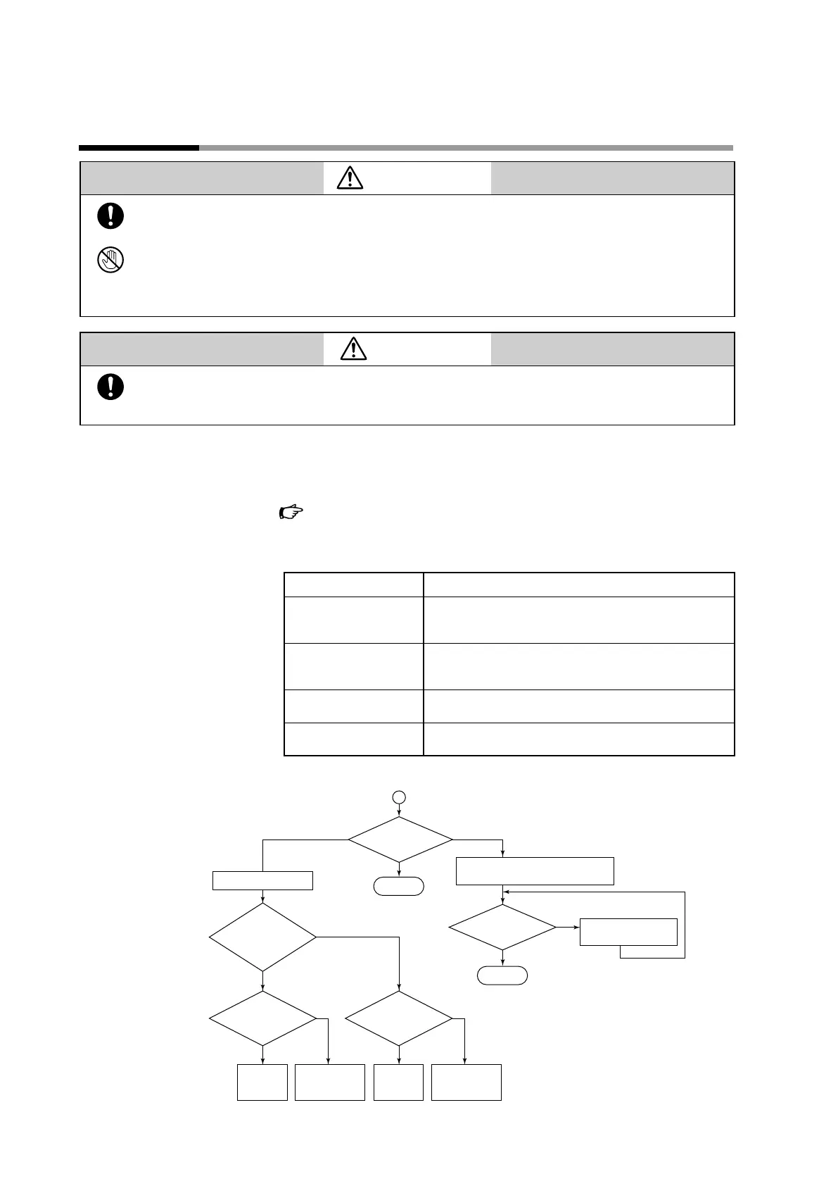
(2)Checktheunitaccordingtotheflowchart.
Check the
ame voltage.*
1
Correct
Zero
OK
Check the
ame voltage.*
1
Adjust the monitoring
position and/or burner.
OK
NG
NG: No good
Small
Replace the
tube unit.
*
4
Check the wiring
and replace the
burner controller.
NG
OK
NO (closed)
YES (open)
• Clean the monitoring window.
• Clean the inside of the monitoring pipe.
Remove the tube unit.
Correct
Does the
shutter open
when power is supplied
to the burner
controller?
Check the
voltage between the
F and G terminals.
*
2
Replace the
shutter unit.
*
4
Check the wiring
and replace the
burner controller.
NG
OK
Check the
shutter voltage.*
3
*1 Normal when 2.0 Vdc or more
*2 Normal when 160 to 220 Vdc
*3 Normal when uctuating between 0 or 15 to 24 Vdc
*4 When replacing the tube unit, replace the shutter unit
also. When replacing the shutter unit, replace the tube
unit also.
Chapter 5. TROUBLESHOOTING
 Loading...