11
Before measurement of flame voltage n
Before measuring the flame voltage, check the operation of this unit through the
flame voltage output terminals of the burner controller.
Model No. Flame voltage output terminals
AUR300C
AUR350C
Terminal 9 (+)
Terminal10 (−)
AUR450C Positive terminal, Negative terminal
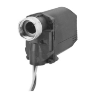
(1) Connect an analog flame meter (FSP136A100) to the flame voltage output ter-
minals of the burner controller.
(2) Light a lighter in front of the ultraviolet ray receiving part of this unit to check
that the voltage is output correctly.
Handling Precautions
When using an open flame, check that there is no flammable gas around this •
unit.
Measurement of flame voltage n
If both pilot flame and main flame exist, measure each flame voltage.
Additionally, measure the flame voltage in the maximum combustion and mini-
mum combustion states.
(1) Mount the monitoring pipe on this unit temporarily.
(2) Start the combustion of the burner.
(3) To determine an optimal monitoring position, measure the flame voltage of the
burner controller with the analog flame meter (FSP136A100) while moving
the monitoring pipe position little by little in order to find a position where as
highly stable voltage as possible is shown.
Recommended flame voltage Inspection item
Stable 2.0 Vdc or more
(The flame voltage may fluctuate
in a range of 0.1 to 0.3 V synchro-
nized with the shutter operation of
this unit.)
Check that the flame is monitored correctly.
Check that the light receiving lens of this unit is
not contaminated.
Check that foreign matter, such as soot is not
caught in the monitoring pipe.
Handling Precautions
When the flame voltage exceeds 4 Vdc, provide an orifice ring into the flange •
unit to limit the quantity of ultraviolet rays. Excess quantity of ultraviolet rays
might cause malfunction by the diffused reflection of ultraviolet rays coming
into the tube unit even when the shutter is closed.
Chapter 4. ADJUSTMENT
 Loading...