Chapter 6. MAINTENANCE AND INSPECTION
17
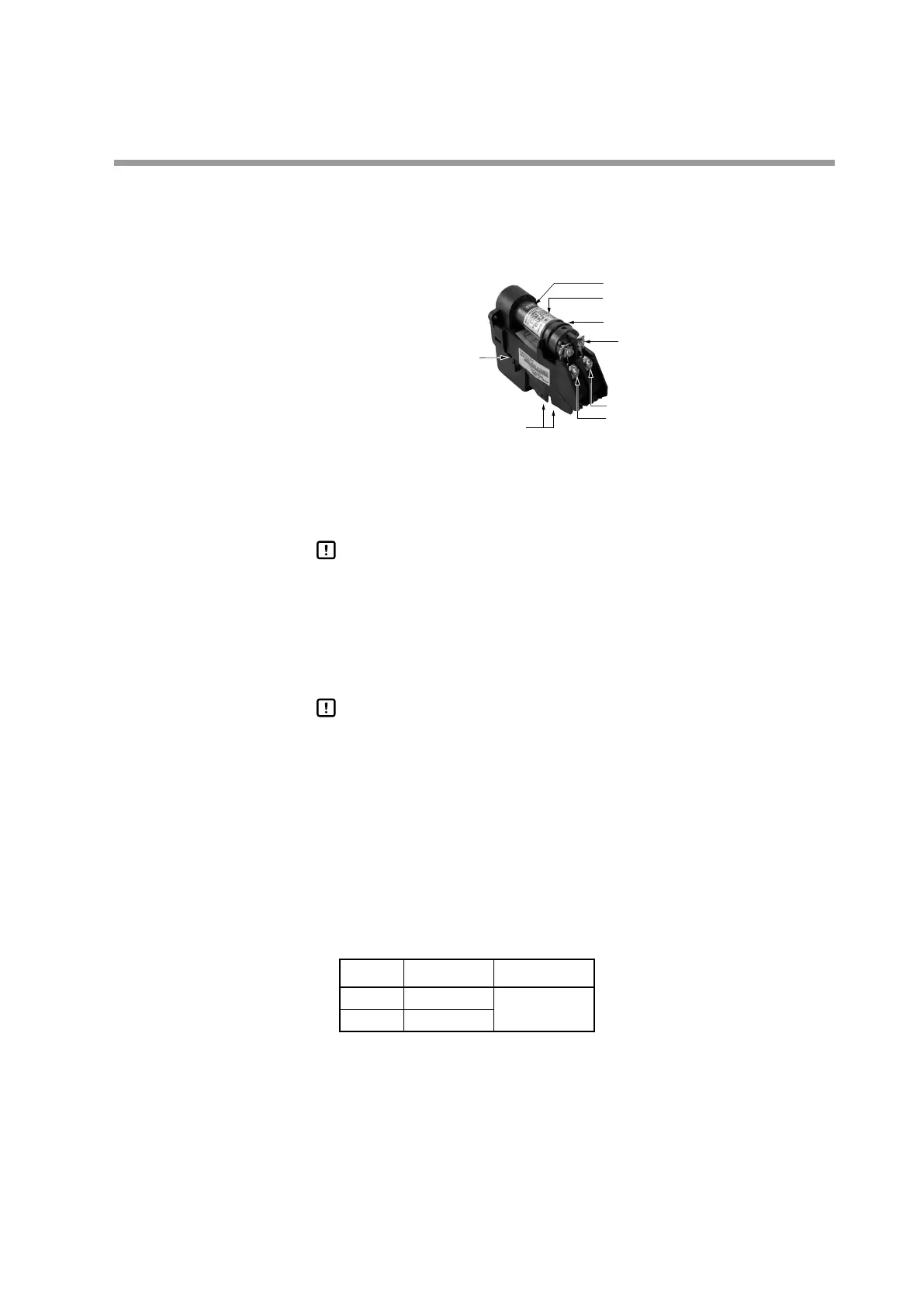
Mounting the shutter unit onto the flange unit ●
(1) Fit the O-ring that is included in the AUD Maintenance Kit onto the flange unit.
(2) Loosen the 2 screws holding the tube unit of the new AUD Maintenance Kit and
then remove the unit, grasping it by the back of the unit.
Terminals for shutter
driver connection
(White lead wire)
Tube unit
Shutter unit
Label
Thermo-label
G terminal (Yellow lead wire)
F terminal (Blue lead wire)
Tube unit
retaining screws (2)
(3) After removing the tube unit, mount the shutter unit only on the flange unit
using the 2 retaining screws.
Handling Precautions
Before mounting, insert the lead wires (blue and yellow) into the slits •
of the shutter unit. When mounting the unit onto the flange unit, hold
the white lead wires under the shutter unit so that they stay in the cable
guide groove.
(4) Be sure to connect the lead wires to the terminals on the shutter unit correctly.
Handling Precautions
Connect the blue lead wire to terminal F and the yellow lead wire to ter-•
minal G. Connect the two wires so that they match the F and G polarity
indication label on the shutter unit.
Wiring check ●
(1) Turn ON the power to the burner controller.
(2) Measure the DC voltage between terminals F and G with a multimeter or digital
voltmeter.
(3) Connect the positive probe to terminal G (yellow lead wire) and the negative
probe to terminal F (blue lead wire).
Terminal Tester Probe Voltage
F −
160 to 220 Vdc
G +
>> If the voltage is between 160 and 220 Vdc, the wiring is correct. If the measured
DC voltage is a negative value, the F and G wires are reversed.
(4) Next, measure the DC voltage between the S1 and S2 shutter voltage terminals
(white wires).
 Loading...