10
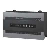
AB-7333
z Installation Method
Figure 5. Example of installation in control panel cabinet
600 mm
1900 mm
700 mm
215 mm from
the panel cabinet
ceiling (highest
level of the
standard layout)
50 mm
50 mm or
more
*1
35 mm or more
50 mm or
more
*1
35 mm
Fan (Model 83978069-101)
• Install one unit at the top of the panel cabinet.
30 mm
30 mm
30 mm duct
30 mm duct
30 mm duct
• Install it at the top of the panel
(right under the fan).
• Install it upright.
Note: Do not tilt it.
• Check that there is clearance for maintenance.
30 mm duct
Power strip
Clearance above and under the product
Air inlet
0.0174 m
2
(198 long oval holes measuring
3 × 30 mm) or larger under the panel door.
40 mm duct
Clearance in front of the product
•
When a device from
which hot air is
exhausted is installed
in the same panel,
install the power strip
underneath the
Supervisory
Controller.
To reduce the effects
of heat radiation,
install high-temperature
devices under the
power strip.
•
Install the Supervisory
Controller, Advanced
Controller, and devices
that do not generate
heat (switching hub,
power failure recovery
circuit, terminal block,
etc.) in the panel.
• The depth should be
60 mm max.
*1 To place the wiring ducts above and under
this product, make sure to leave a
clearance of 35 mm or more.
35 mm
Supervisory Controller
Model BH-101G0_0000
60 mm duct

 Loading...