AB-6528
10
Wires Connection
Connection to the power supply terminal block
Crimp the terminal lugs for the M3 screw terminal block to the
wire ends, and connect them to the terminal block.
Connection to I/O modules and NC-bus terminal block
Since quick-fit screwless terminal block is used for the I/O
modules and the NC-bus terminal block, the procedure for
connection is specified as follows.
1) Strip the wire sheath 8 mm. (The gauge for the strip
length is located at the front lower part of Infilex GC basic
unit. If the stripped part is longer than 8 mm, the
conductor will be exposed, causing electrical shock or
short circuit between adjacent terminals. If it is shorter,
the conductor may not contact the connector.)
2) Make sure that no wire fiber is protruded from the
conductor (stripped wire).
3) Press the button on the terminal block deeply enough to
insert the wire using a slotted screwdriver.
(Maximum button-pressing force is 14 N.)
4) Release the button, and gently pull out the wire
horizontally to make sure that it is tightly fastened. (If you
pull out the wire diagonally, it may be disconnected.)
Make sure that no wire fiber is protruded from the
conductor (stripped conductor).
Positions for connected wires
Neatly place the wires, using cable ties or the like, connected
to Infilex GC so as not to hide LED, Data Setter connector, ►
mark, S1 switch, battery holder, or indication tag, as shown in
Fig. 8.
Make sure there is no slack in the wires from the cable ducts
to Infilex GC.
Figure 8. Connected wires in position (example)
Tube marker
Since Infilex GC adopts a quick-fit screwless terminal block,
wires are connected without crimp terminals. Therefore, if
normal tube markers are used, they may come off when the
wires are disconnected. To prevent this, use the following
Flat Tube Marker. It is held on a wire by friction and thus
does not come off easily.
Manufacturer Phoenix Contact
Part name Flat Tube Marker
Part number 5880029
Model TMC-3
Applicable wire size 0.4 mm
2
to 2 mm
2
Package unit 200 m/roll
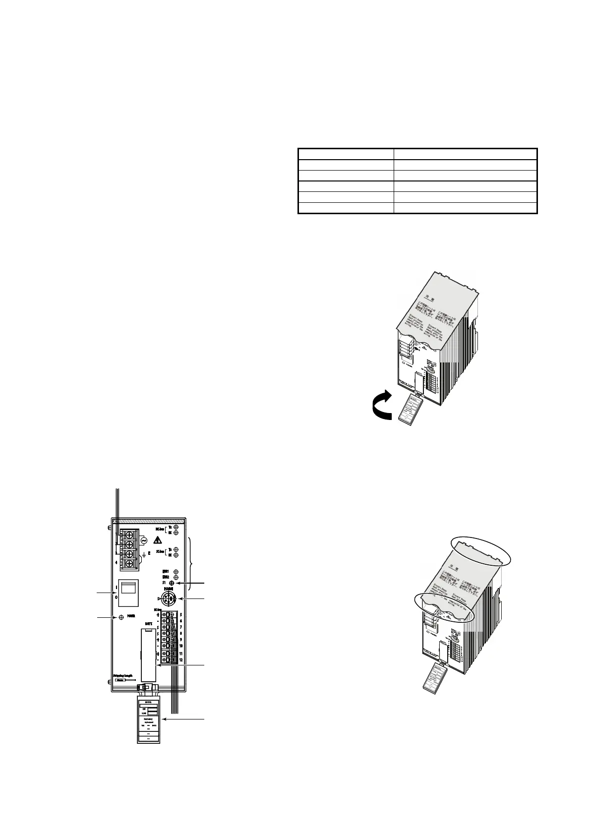
System indication label for the controller number
The indication tag has the system indication label on its back.
Turn it over and fill in the controller number on the label.
Figure 9. System indication label
Protective sheet
After connecting the wires, be sure to peel off the protective
sheet before turning on the power.
1) Adhesive is applied to the sheet approximately 20 mm
from the front edge. Peel off this area.
2) Tear off the sheet along the perforations.
Figure 10. Protective sheet
2) Tear off.
1) Peel off the adhesive area.
S1 switch
Connector for
Data Setter
Battery holder
Indication tag
LED
Power switch
LED
Indication tag
Turn over.

 Loading...


