AB-6528
7
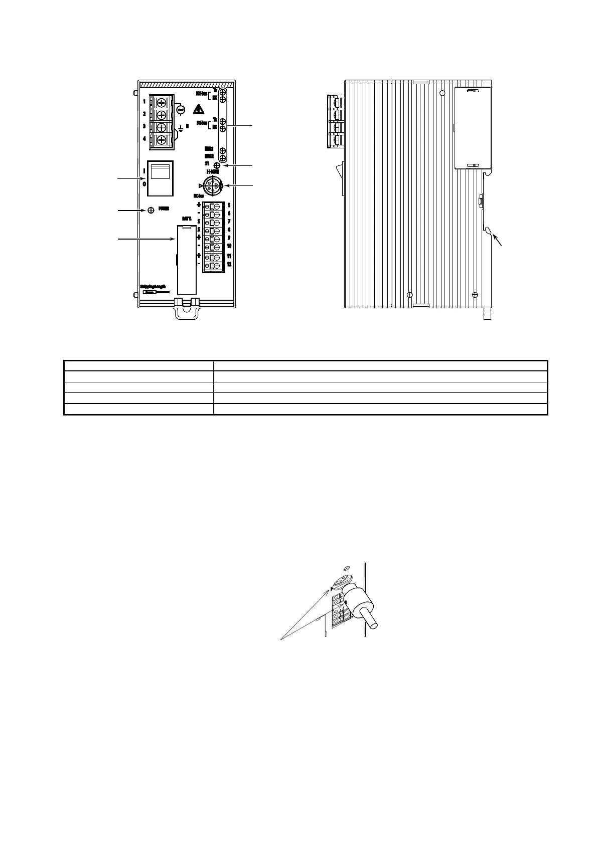
Parts Identification
Figure 4. Parts identification
Table 1. Indication and operation of operating status LED
LED indication LED operation
Data transmitting NC-bus TX LED: flashing
Data receiving NC-bus RX LED: flashing
Major failure / system restart ERR1: ON
Minor failure / system restart ERR2: ON
Connection of Data Setter (H-MMI) / PC-MMI
1) Connection of Data Setter Model QY5111B
No conversion cable is required. Directly insert the male connector of the Data Setter into the female connector provided on
the Infilex GC basic unit.
At this time, hold the male connector with the ◄ mark facing left and insert it as the mark points to the ► mark on the
Infilex GC basic unit.
2) Connection of Data Setter Model QY7211B / PC-MMI
Convert the D-SUB connector to the mini DIN connector with the conversion cable (Part No. 83104995-001).
At this time, hold the male connector with the ◄ mark facing left and insert it as the mark points to the ► mark on the
Infilex GC basic unit.
Figure 5. Connecting Data Setter/PC-MMI
Insert the male connector as
the two arrows point to each
other.
DIN rail
mounting
hook
Do not press the S1 switch.
S1 switch*
Connector (female)
for Data Setter
Power switch
LED fo
Power ON/OFF
Battery holde
LED for
operating status

 Loading...


